Electrical connection – GEA Bock BCM2000 User Manual
Page 7
7
D
GB
F
E
09794
-05.2012-DGbFEI
orange brown red
C
B
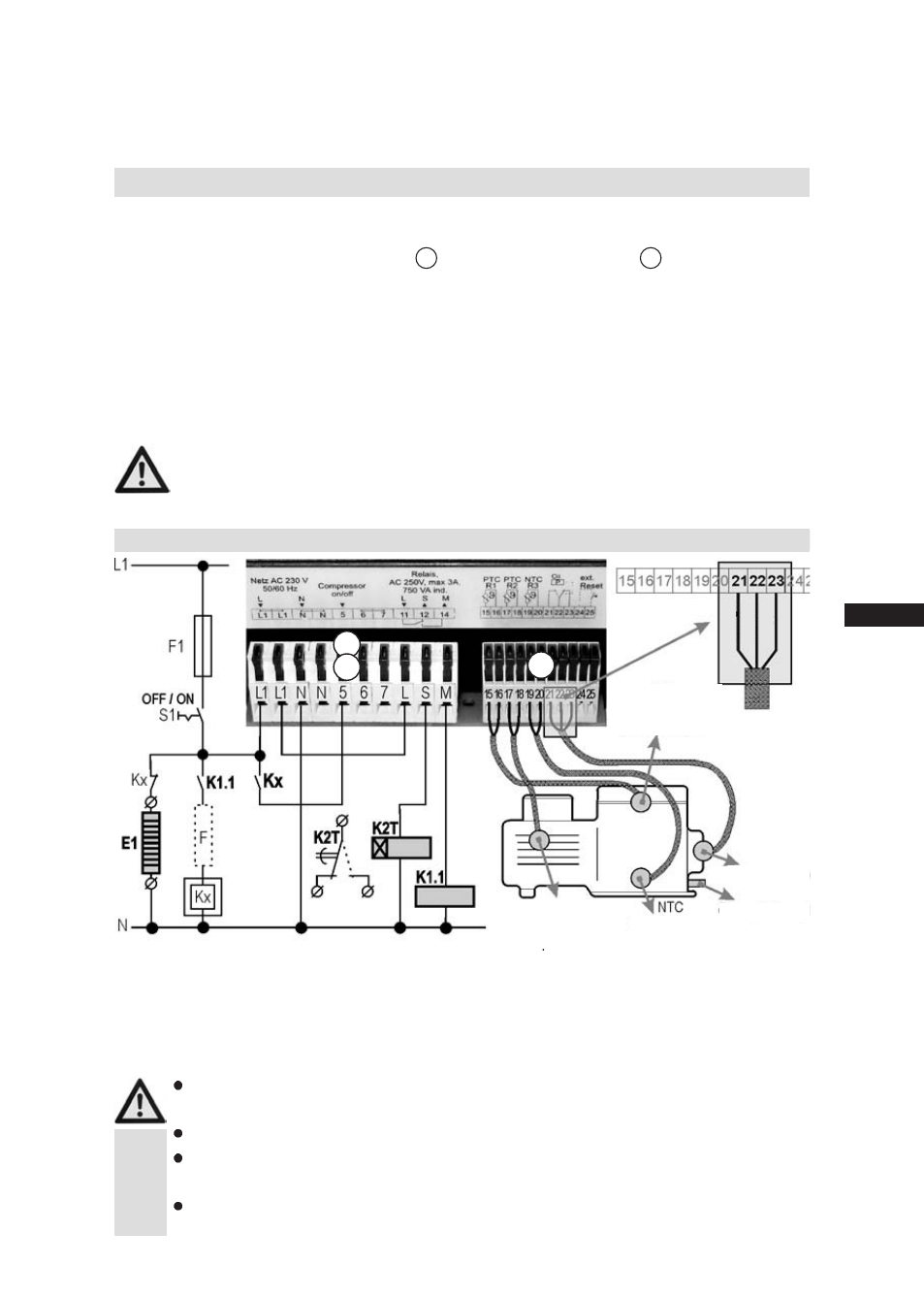
E1 Oil sump heating
F1 Control fuse
K1.1 Auxiliary contactor
K2T Delay relay 10 - 60 min
F
Safety chain with regulating unit (thermostat)
Kx Compressor load contactor or protection
combination with motor protection switches
S1 Switch for control voltage OFF/ON
Connecting the unit
Electrical connection of the unit is to be carried out by a qualifi ed electrician
according to the circuit diagram.
Comply with the local safety regulations.
Always disconnect the machine from the power supply before and during working
on the machine.
Compare the voltage and frequency details on the nameplate with the details for the
electricity mains. Unit may only be connected up when these coincide.
PTC
compressed gas
temperature sensor
PTC
motor winding
temperature sensor
oil temperature
sensor
oil pressure
sensor
oil sump
heating E1
brown red
orange
Electrical connection
B
C
E1 Oil sump heater
F1 Control fuse
K1.1 Auxiliary contactor
K2T Delay relay 10-60 min.,
Connection facility for external
collective error message
F
Safety chain with regulating unit (thermostat)
Kx Compressor load contactor or protection
combination with motor protection switches
S1 Switch for control voltage Off / On
Connecting the unit
Electrical connection of the unit is to be carried out by a qualified electrician accor-
ding to the circuit diagramm.
Comply with the local safety regulations.
Always disconnect the machine from the power supply before and during working
on the machine.
Compare the voltage and frequency details on the nameplate with the details for
the electricity mains. Unit may only be connected up when these coincide.
Electrical connection
General
The unit has two different connection blocks:
1) Power supply section B
2) Control section C
The power supply section is for connection to the machine mains voltage. It is to be integrated in the
machine control by the refrigerating engineer (qualifi ed engineer). The unit is to be integrated in fi rst
position of the safety chain. The power supply at L1-N should be identical with the switching voltage
at relay contacts 11, 12 and 14.
The control section is used for connection of the individual monitoring functions. These are normally
ready wired in the factory and prefabricated ready for operation so that no additional work is neces-
sary here.
The whole control section (terminals 15 - 25) and all monitoring sensors, probes and
corresponding connections must not have any contact with mains voltage. Otherwise
the BCM 2000 and sensor components will be destroyed.
Electrical connection