Product description, Structure / functions – GEA Bock BCM2000 User Manual
Page 5
5
D
GB
F
E
09794
-05.2012-DGbFEI
Product description
Structure / functions
The BCM 2000 is used solely for monitoring the operation of BOCK refrigerating compressors. All
monitoring parameters have been coordinated exactly to the compressor connected up in the factory.
Incoming signals are detected as status, information or error messages and processed to release,
shutdown and reporting functions. The unit does not exercise any regulating function.
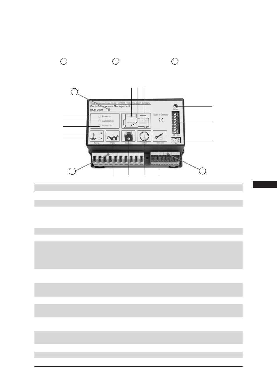
The unit has three main components:
A - Electronic section B - Power supply section C - Control section
Altogether the unit has 8 monitoring functions: motor winding temperature, compressed gas tempera-
ture, oil temperature, oil pressure, liquid detection during start-up, compressor rotation detection,
surge guard, recommended oil change.
A
B
C
12
11
4
9
10
6
5
15
14
13
8
7
2
3
1
Item No. Designation
Function
1
Mains voltage
LED green for mains voltage
2
Compressor operation
LED green for compressor operation
3
Automatic compressor start
LED yellow for automatic compressor release. Com
pressor starts after a delay via the machine
control or lube oil pre-heating
4
Motor winding temperature
LED red
when temperature too high
5
Compressed gas temperature LED red
when temperature too high
6
Oil temperature
LED red
when temperature too low
Compressor is enabled for starting only
when the lube oil is pre-heated to +25°C,
but at the latest after 30 min.
7
Temperature display +
LED red
comb. with item 4 / 5 / 6
8
Temperature display -
temperature too high (+) or too low (-)
9
Oil pressure
LED red
when oil pressure too low
Delay: approx. 90 s
10
Liquid detection
LED red
for liquid hammers during start-up
10
Compressor rotation detection LED red
when compressor does not start although
motor supplied with power
11
Surge guard
LED yellow for more than 12 starts per hour
Compressor continues to operate, no stop
12
Recommended oil change
LED yellow after a certain interval has been exceeded
Compressor continues to operate, no stop
13
Reset button
Reset to operating function
14
Bridging switch
Activates or bridges individual functions
15
PC interface
For reading
}