Appendix system a - 100, Doepfer – Doepfer A-100NT5 +5V Power Supply User Manual
Page 46
9. Appendix
System A - 100
doepfer
36
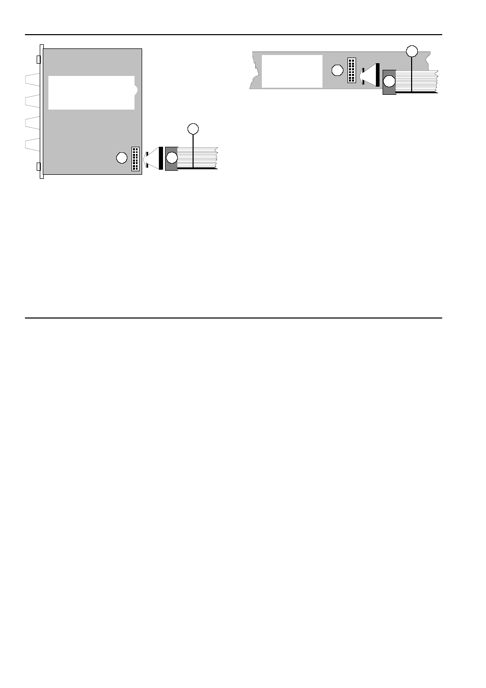
Fig. 1:
Connecting the ribbon cable to the module
D
Now join the free end of the ribbon cable (see
2
in
Fig. 2) to the nearest available position on the
system bus board (see
1
in Fig. 2).
A
Again ensure that the coloured marking on
the ribbon cable is at the bottom of the
module’s connector (see
3
in Fig. 1) and
that the connection is perfect, and pushed
fully home, not at a slight angle. Failure to
check this may again result in disaster.
Fig. 2:
Connecting the ribbon cable to the bus
board.
D
Now fix the module solidly in its case.
D
Re-connect the A-100 MNT’s power supply, and
then switch on the mains again.
D
Test out the newly installed module.
If it doesn’t seem to be working as expected, imme-
diately disconnect the system from the power sup-
ply again.
In this case, double-check the connections, making
completely sure that the ribbon cable is the right
way round where it connects to the module and to
the bus.
Bestückungsseite
1
3
2
3
2
1
Busplatine
components side
bus board