Ignition – Cub Cadet CC 4BP 32cc User Manual
Page 18
Ignition
15
2.
To test the module:
2a. Remove the blower housing as described in
the blower housing chapter of this manual
to expose the module.
2b. Check the air gap for the module. Set it to
.010 (.25 mm) by following the steps
described in the module section of this
chapter.
2c. Disconnect both wires. See Figure 4.3.
2d. Try to start the engine with the spark tester
still hooked up.
•
If there is spark now, test the engine kill switch
and check the black wires for a short to ground.
•
If there is still no spark, hold a screwdriver
against the magnets on the flywheel to feel if
they are magnetic.
•
If the magnets are good, replace the module. If
not replace the flywheel.
3.
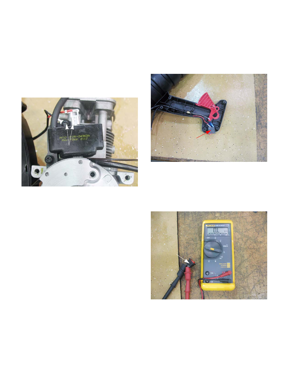
To test the engine stop switch:
3a. Open the grip by removing the eight
screws
with a T-25 driver.
3b. Disconnect the wires from the engine kill
switch. See Figure 4.4.
3c. Connect an ohm meter or continuity light to
the switch.
3d. With the switch in the engine run position (l),
the meter should indicate no continuity.
See Figure 4.5.
NOTE: Most stop switches are spring loaded to
the run position when it is released. This pre-
vents no-start situations caused by the customer
failing to turn the switch on.
Figure 4.3
Disconnect both
wires
Figure 4.4
Remove wires from switch
Figure 4.5
Switch in the engine
run position