Checkline ETMPB User Manual
Page 3
– 3 –
2.0 OVERVIEW
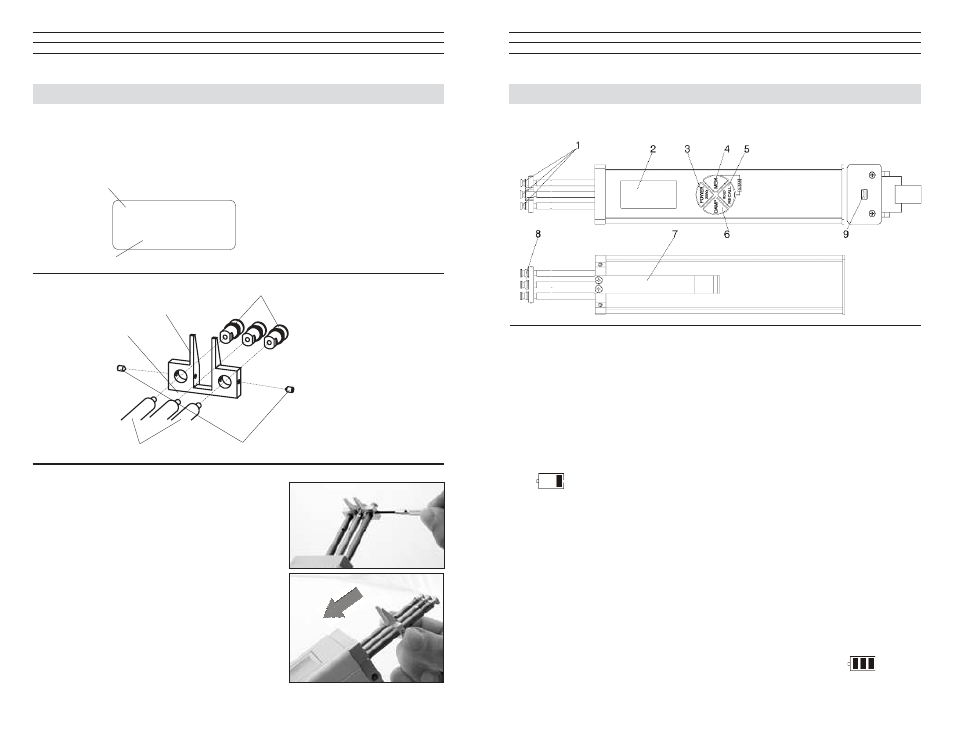
2.1 Operating Elements
6 DAMP key
7 LEVER
8 FILAMENT GUIDE
9 USB output (for connecting
the AC adapter
1 ROLLERS or ceramic pins
2 DISPLAY
3 POWER / ZERO key
4 MEM key
5 RECALL / HOLD key
2.2 Battery Management & Charging
The tension meter has a built-in rechargeable LiPo battery, which has been charged at
the factory. The tension meter can only be switched on if the battery has enough charge.
If the instrument does not power up or if the battery level indicator shows only one bar
after power-up the battery needs to be recharged.
NOTE: To ensure maximum battery life, avoid discharging it completely or charging it
frequently for short periods. The battery should not be stored for a prolonged time when
empty. After a maximum storage period of one year, the battery has to be recharged.
Charging the Battery
NOTE: The battery must be charged at a temperature between +5 °C and
+45 °C. Before connecting the AC adapter, verify that the supply voltage is
correct (100 V – 240 V). Electromatic provides no warranty or liability for
damage resulting from the use of AC adapters from other manufacturers.
To charge the battery, connect the cable of the AC adapter to the USB output. When
the battery is fully charged, the battery level indicator will show 3 bars
.
The charging time is approx. 3 ½ hours. Battery overcharging is not possible.
–18 –
10.0 APPENDIX - REPLACING THE ROLLERS/CERAMIC PINS
You should regularly inspect the rollers to assure that they are running easily and
smoothly. You can replace the rollers yourself, as necessary, by following the directions
in this section. Please indicate the tension meter model and the serial number (given on
the rear side of the tension meter) in your spare-parts order.
Model: 03/04
ETMB-100
#
400 - 88888
Model ID
Serial number
NOTE: Replacing rollers with
ceramic pins or ceramic pins with
rollers can only be performed at
the manufacturer’s facility.
GUIDE ROLLERS (2x)
ROLLER SHAFTS (2x)
FILAMENT GUIDE
GRUB SCREWS (2x)
MEASURING ROLLER
Procedure
1. Remove the FILAMENT GUIDE by loosening
the SETSCREWS (2) using the
supplied screwdriver (1.5m blade width).
2. Slide the FILAMENT GUIDE down the
ROLLER SHAFTS in the direction of the
arrow.