Checkline WTTM-GEN1 User Manual
Page 10
– 10 –
7.0 O
PERATING
P
ROCEDURES
7.1. Switching on the instrument, selecting the measurement unit and
operational mode
1. Switch on the instrument by pressing the
ON/OFF
button.
After a power-up self test and calibration (approx. 20 sec.), the display will
indicate the last selected measuring unit, function and the value 0.00.
2. Select the desired operation mode (indication of the current measurement
value or the peak value) and the measuring unit by pressing the
PEAK
and
MODE
buttons simultaneously. The current settings will be indicated on the
display. When you choose the
PEAK
mode, the peak value will be always
indicated on the display (drag indicator function).
7.2. Resetting to zero before each measurement
It is necessary to zero-set the instrument before starting
each pull force measurement. Press the
RESET
button
for this purpose. The
RESET
button can also be used
for deleting the peak value updated in the memory.
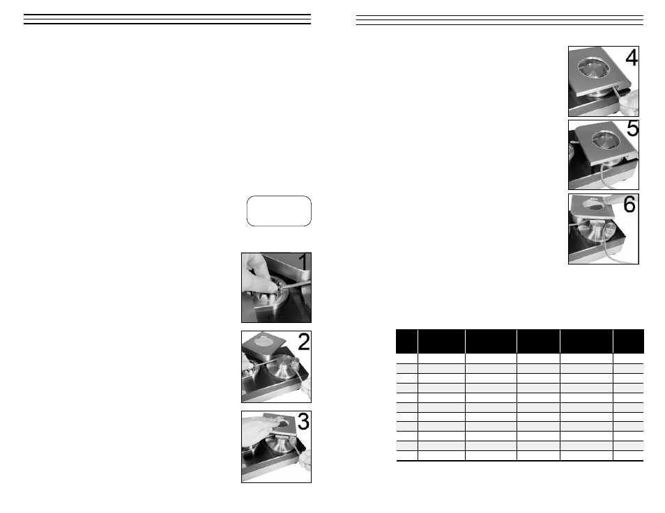
7.3 Taking Measurements
NOTE:
Select the smallest suitable slot for the test
sample diameter.
1. Place the cable connection into the adapter, so
that the sleeve of the cable connector stays
securely inside the ring and cannot be pulled out
through the slot.
2. Insert the free cable end with slight tension into
the
clamping fixture
. The nut in the pull force
fixture
will help you to find the right position
for the cable.
3. Holding the cable tight and securely, close the
protection cover.
N
0.0
– 11 –
4. The motor starts and closes the pull force
fixture. Hold the cable end securely until the
pull force develops.
5. The rotational motion of the pull force fixture
tears off the cable from the terminal joint. The
motor stops when the maximal pull length has
been reached.
6. When you open the protection cover, the pull
force fixture returns back to the original
position and releases the cable.
7. During the measurement, the force progression
can be read off the display.
The peak value, which mostly appears before the
connection breaks, is captured at 1000Hz and is
indicated when the
PEAK
button is pressed (so
long as the drag indicator function was not active).
Depending on the wire strength and the related standard, the following
tensile strength should at least be achieved.
AWG
Cross-Section
Cable Diameter
SAE AS7928
IEC 60352 Part2
UL 486 C
Table II
30
0.06 mm_
0.36 mm
6 N
6 N
28
0.09 mm_
0.38 mm
11 N
11 N
26
0.14 mm_
0.48 mm
32 N
18 N
18 N
24
0.22 mm_
0.61 mm
45 N
28 N
28 N
22
0.34 mm_
0.76 mm
67 N
40 N
40 N
20
0.56 mm_
0.97 mm
85 N
60 N
45 N
18
0.93 mm_
1.27 mm
170 N
90 N
45 N
16
1.25 mm_
1.44 mm
223 N
135 N
68 N
14
1.93 mm_
1.80 mm
312 N
200 N
100 N
12
3.16 mm_
2,29 mm
490 N
275 N
138 N
10
4.65 mm_
3.10 mm
355 N
* DIN IEC 60352 Part 2 replaces DIN 4161/3 ** SAE AS7928 Table II replaces MIL-T-7928
BS5B178 corresponds to IEC 60352 Part 2 UL486A corresponds to IEC 60352 Part 2