Checkline WTT-110 User Manual
Page 7
– 7 –
9 .0
G
EN ERAL
O
PERAT I N G
P
ROCEDU RES
1. Press On/Off key. During power-up, the WTT-110 performs a self-test routine.
During this procedure, the maximum capacity of the system will be temporarily
displayed in selected units of measurement. Then the unit should display zero.
Occasionally the last one or two digits might be something other then zero.
Additionally, the selected units will be shown.
2. Select the desired operation mode. To set for Peak Capture Mode, press the PEAK
key once. The peak indicator will be shown on the display when the system is set
for peak capture mode (highest value measured and stored until reset to zero). To
set for Average Mode, make sure the peak indicator is not shown. Press the PEAK
key until indicator is no longer illuminated. In this mode, the display is constantly
updated 3 times per second .
Note:
The Display Update Rate can be set to update 1, 2, 3, 5, 10 or 20 times per
second (5 times per second = 0.2 seconds). Refer to Advanced Setting, section
10.4, page 11 for additional information and to change the update rate.
3. It is necessary to zero-set (“tare”) the WTT-110 before starting each force measure-
ment. Press the ZERO key for this purpose. The ZERO key is also used for clearing
the currently stored Peak value from display memory whenever desired.
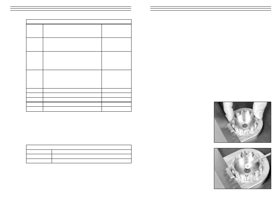
4. Select the smallest suitable slot in the
Wire Terminal Fixture based on the
diameter of the wire and the physical
dimensions of the connector. Rotate
the fixture so the selected slot is in
the 3 o’clock position so it is closest
to the Wire Clamp Fixture.
5. Place the cable connection into the
fixture such that the main part of the
connector is retained on the inside of
the fixture and the sleeve and cable
will pass through the slot toward the
Wire Clamp Fixture. When pulling
on the cable, the terminal should be
well secured.
– 14 –
11.2 Analog Output
The analog output (-1...0...1 VDC) can be used for any data acquisition or data
recording device. Pull Force data will be expressed as a negative voltage. The
signal can be set to zero (reset) by performing a ZERO (tare) function. +1 VDC
and – 1VDC refers to the maximum and miniuml full scale (end of nominal
measuring range).
PROTOCOL CODE
Extern >>
Average data output
NA®®®®®®cr
3. digit:
+ /or –
4.-6. digit. Value incl. floating decimal point
Peak data output
NB®®®®®®cr
3. digit:
+ /or –
4.-6. digit. Value incl. floating decimal point
Unit: 3 digit
0 = N
1 = kg (g)
3= lb (oz)
NH®cr
Unit: 3 digit
NH®cr
0 = N
1 = kg (g)
3= lb (oz)
Error
OBcr
Command Error
OEcr
Parity Error
OFcr
Format Error
OGcr
Summing Error
OHcr
Overflow
SPECIFICATION
Amplitude
-1VDC / +1VDC
Signal generator
12-bit D/A-Converter
Signal update
100 Hz