1 display panel – Checkline FGS-100PX User Manual
Page 6
6
4.1 Display Panel
MIN
MAX
MIN
MAX
A
B
SPEED
L I M I T
A L A R M
OVERLOAD
No
TIME
LENGHT
SPEED
ZERO
SEC
PROG
CO
NT
JOG
MANU
SNG
PULL
PUSH
STOP
MODE
TIME
SET
RST
PROG
START
1
5
4, 6, 7
9, 10, 11
20
21
2
3
13
14
15 8
18
17
16 12 19
24
22
23
25
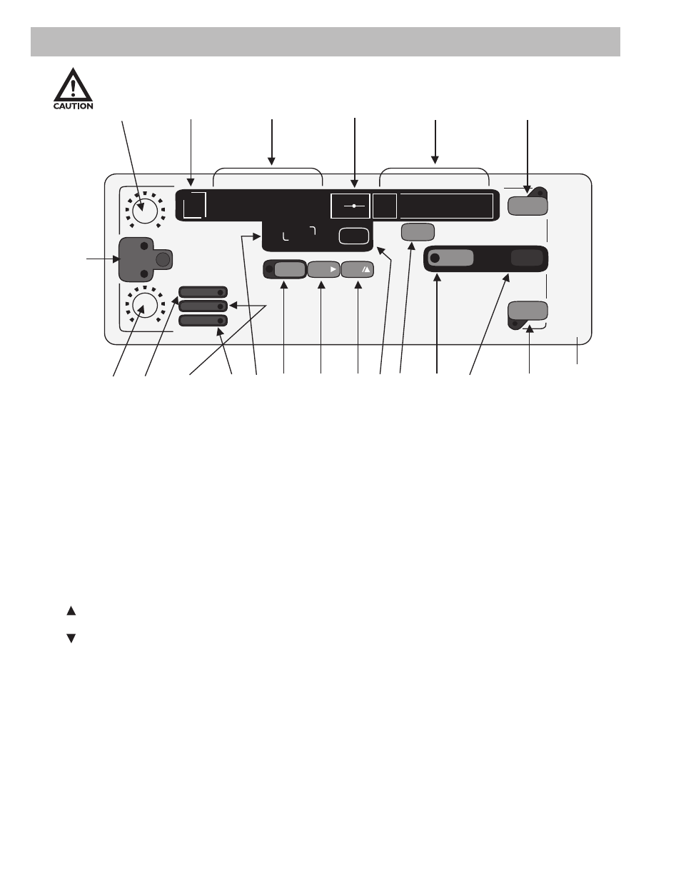
4.1 Display Panel
Figure 1
1. A Speed: Changes the left movement or upward speed (Continuous and Program Mode).
2. B Speed: Changes the right movement or downward speed. (Continuous and Program
Mode).
3. Speed: Selects speed control knob A or B.
4. Length, Speed or Cycle Display: Displays length, speed or cycle of a program when power
is on. Note: Cycle Display can only be selected in mode SING, CONT or PROG.
5. No: Displays program cycle (0-9).
6. : Indicates high limit value in all modes.
7. : Indicates low limit value in all modes.
8. TIME: Displays programmed delay time between program cycles.
9. LENGTH, SPEED, or Cycle: Selects display of length, speed or cycle of a program.
10. LED LENGTH Indicator: Indicates that length is being displayed.
11. LED SPEED Indicator: Indicates that speed is being displayed. Cycle display is indicated
when both Length and Speed LED’s are off.
12. ZERO: Resets length measurement to zero.