Pin definitions – Cypress HOTLink II CYV15G0104TRB User Manual
Page 8
CYV15G0104TRB
Document #: 38-02100 Rev. *B
Page 8 of 27
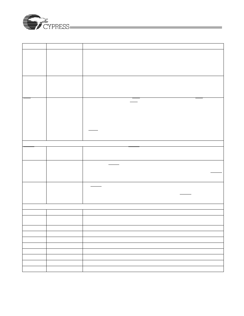
SPDSELA
SPDSELB
3-Level Select
[4]
static control input
Serial Rate Select. The SPDSELA and SPDSELB inputs specify the operating signaling-
rate range of the receive and transmit PLL, respectively.
LOW = 195 – 400 MBd
MID = 400 – 800 MBd
HIGH = 800 – 1500 MBd.
INSELA
LVTTL Input,
asynchronous
Receive Input Selector. The INSELA input determines which external serial bit stream
is passed to the receiver’s Clock and Data Recovery circuit. When INSELA is HIGH, the
Primary Differential Serial Data Input, INA1±, is selected for the receive channel. When
INSELA is LOW, the Secondary Differential Serial Data Input, INA2±, is selected for the
receive channel.
LFIA
LVTTL Output,
asynchronous
Link Fault Indication Output. LFIA is an output status indicator signal. LFIA is the logical
OR of six internal conditions. LFIA is asserted LOW when any of the following conditions
is true:
• Received serial data rate outside expected range
• Analog amplitude below expected levels
• Transition density lower than expected
• Receive channel disabled
• ULCA is LOW
• Absence of TRGCLKA±.
Device Configuration and Control Bus Signals
WREN
LVTTL input,
asynchronous,
internal pull-up
Control Write Enable. The WREN input writes the values of the DATA[6:0] bus into the
latch specified by the address location on the ADDR[2:0] bus.
[5]
ADDR[2:0]
LVTTL input
asynchronous,
internal pull-up
Control Addressing Bus. The ADDR[2:0] bus is the input address bus used to configure
the device. The WREN input writes the values of the DATA[6:0] bus into the latch specified
by the address location on the ADDR[2:0] bus.
[5]
Table 4 lists the configuration latches
within the device, and the initialization value of the latches upon the assertion of RESET.
Table 5 shows how the latches are mapped in the device.
DATA[6:0]
LVTTL input
asynchronous,
internal pull-up
Control Data Bus. The DATA[6:0] bus is the input data bus used to configure the device.
The WREN input writes the values of the DATA[6:0] bus into the latch specified by address
location on the ADDR[2:0] bus.
[5 ]
Table 4 lists the configuration latches within the device,
and the initialization value of the latches upon the assertion of RESET. Table 5 shows how
the latches are mapped in the device.
Internal Device Configuration Latches
RXRATEA
Internal Latch
[6]
Receive Clock Rate Select.
SDASEL[2..1]
A[1:0]
Internal Latch
[6]
Signal Detect Amplitude Select.
TXCKSELB
Internal Latch
[6]
Transmit Clock Select.
TXRATEB
Internal Latch
[6]
Transmit PLL Clock Rate Select.
TRGRATEA
Internal Latch
[6]
Reclocker Output PLL Clock Rate Select.
RXPLLPDA
Internal Latch
[6]
Receive Channel Power Control.
RXBISTA[1:0] Internal Latch
[6]
Receive Bist Disabled.
TXBISTB
Internal Latch
[6]
Transmit Bist Disabled.
TOE2B
Internal Latch
[6]
Transmitter Differential Serial Output Driver 2 Enable.
TOE1B
Internal Latch
[6]
Transmitter Differential Serial Output Driver 1 Enable.
Notes:
4.
3-Level Select inputs are used for static configuration. These are ternary inputs that make use of logic levels of LOW, MID, and HIGH. The LOW level is usually
implemented by direct connection to V
SS
(ground). The HIGH level is usually implemented by direct connection to V
CC
(power). The MID level is usually
implemented by not connecting the input (left floating), which allows it to self bias to the proper level.
5.
See Device Configuration and Control Interface for detailed information on the operation of the Configuration Interface.
6.
See Device Configuration and Control Interface for detailed information on the internal latches.
Pin Definitions
(continued)
CYV15G0104TRB HOTLink II Serializer and Reclocking Deserializer
Name
I/O Characteristics
Signal Description