Installation installation, 7 water connection – STIEBEL ELTRON Accelera 300 User Manual
Page 18
18
| ACCELERA® 300 HEAT PUMP WATER HEATER
WWW.STIEBEL-ELTRON-USA.COM
INSTALLATION
INSTALLATION
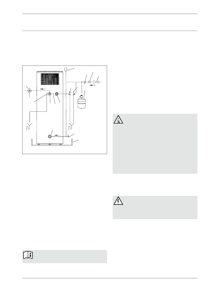
10.7 Water connection
The water connection must be carried out by a qualified licensed
plumber.
The cold water connection must comply with DIN 1988 [or state
and local codes]
» Prior to installing the water heater, flush the line thoroughly.
H
M
C
1
5
6
2
3
4
Cold water
7
8
9
10
Hot water
13
14
12
11
26
_03
_01
_11
23
15
1 Vacuum breaker
2 Hot water connection (Union adaptor to 3/4")
3 Mixing valve (optional, supplied by installer)
4 Connection for T&P valve ¾"
5 T&P valve ¾", 0.69 MPa @99 °C (100 psi @210 °F) (supplied
with unit)
6 0.551 MPa (80 psi) relief valve (optional, supplied by
installer)
7 Expansion tank (optional, supplied by installer)
8 Straight-through shut-off valve (supplied by installer)
9 Check valve (optional, supplied by installer)
10 0.48 MPa (70 psi) pressure reduction valve (optional,
supplied by installer)
11 Cold water connection (with Union adaptor to 3/4")
12 Condensate drain (elbow supplied with unit)
13 Drain valve (supplied by installer)
14 Drain pan (supplied by installer)
15 Condensate spillover
» Remove the protective rubber caps from the connectors.
» With a sharp knife, cut a hole into the protective caps and
install them over the pipe to be connected.
» Connect the plumbing.
» After connecting the plumbing, connect the protective caps
so that the sheet steel casing of the water heater grips into
the outer groove of the protective cap.
Risk of damage through corrosion
To protect against the risk of corrosion, make the
connection with flat gaskets.
» Insulate the hot water line against heat loss.
» Install a drain valve at the lowest point of the cold water
supply.
Install a 0.48 MPa (70 psi) pressure reducing valve on the cold
water inlet.
Accurately maintain the order of fittings on the cold water side
(see diagram 10.7).
10.7.1 Safety valve (on-site provision)
This water heater is a sealed unit. A 0.69 MPa, 99 °C (100 psi,
210 °F) T&P relief valve must be installed.
When installing the T&P valve, observe the following:
- Size the drain line so that water can drain off completely,
even if the safety valve is fully open.
- The drain outlet must not be able to be closed and must
always remain open to atmosphere.
- The T&P valve must open at a pressure of 0.69 MPa (100 psi)
and be 3/4" pipe thread.
10.7.2 T&P valve (on-site provision)
WARNING Risk of injury through excessive pressure
and temperatures.
Install safety equipment that meets the applicable
regulations for the installation locations. In any case
install a "Pressure and Temperature Relief valve (T&P
relief)" that complies with the requirements of the
ANSI Z21.22 ("Requirements for Relief Valves and
Automatic Gas Shut-off Water heaters for Hot Water
Supply Systems").
The T&P valve must respond at a pressure of 0.69 MPa
(100 psi). Fit the T&P valve into the opening on the
circumference of the water heater indicated.
Ensure that any expelled water cannot come into
contact with 'live' parts and will not run onto sensitive
surfaces. Ensure that the T&P valve outlet remains
free at all times.
10.8 Power supply: 240V / 15A double pole
circuit breaker
The electrical connection must be carried out by a qualified
electrician.
DANGER Electric shock
Contacting 'live' components results in a risk to life.
»
Disconnect the water heater from the power supply
before carrying out work on the control panel.
»
Be sure that no one can reconnect the power while
you are working.
When making a connection use code compliant disconnects.
» Undo the screws and remove the water heater cover.