Caution, Control panel, Operating status – Steffes 9180 User Manual
Page 6
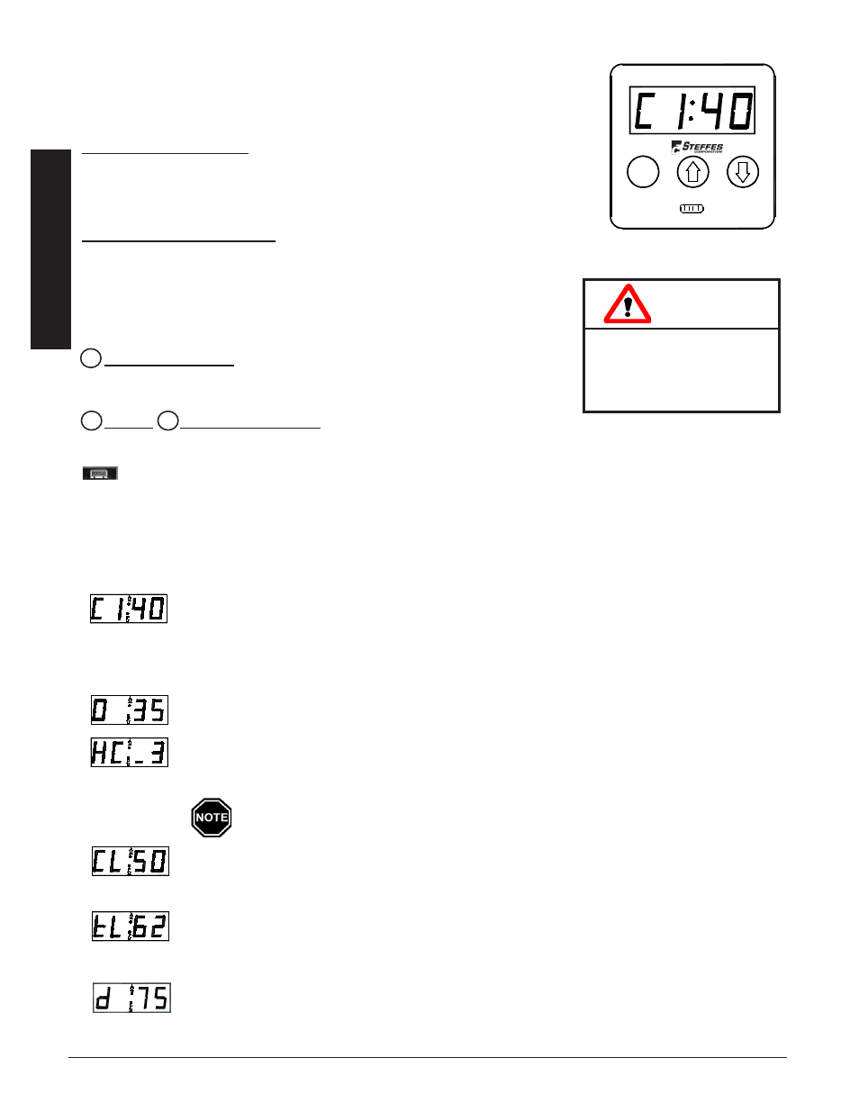
control Panel
Operation of the ThermElect Hydronic system is automatic. All operational func-
tions are stored in its microprocessor in function locations and are factory preset. If
necessary, the installer can adjust them through the control panel. (See Figure 1.)
Four-digit LEd display
The four digit LED displays specific operating information. During the configura-
tion process, the configuration number and the values set in these configurations are
displayed for viewing and adjusting purposes.
aM and PM Indicator Lights
The AM and PM indicator lights are only utilized if the Steffes Time Clock Module
is being installed and using 12 hour time display. With this module installed,
the system displays time on AM/PM intervals. The light flashes next to the ac-
tive designator/symbol. The system can be configured to display military time,
in which case both the AM and PM lights illuminate.
Mode (Edit) Button
Used to access menus on the system (i.e. Help Menu or Configuration Menu)
and to allow modifying of configuration settings.
Up and down arrow Buttons
Used to scroll up or down when viewing or modifying operating functions.
Interface Port
Allows technician external access for advanced operating modes, updating software, and troubleshooting.
oPeratinG StatuS
The four digit LED will display various operating information as described below. Press and release the up arrow
to view this data.
Operating Mode - Indicates the current operating mode of the system followed by the outlet
water temperature.
C = Off-Peak (Charge) Time
P = On-Peak (Control) Time
A = Anticipated Peak Time
Outdoor Temperature -“O” followed by a number indicates current outdoor temperature.
Heat Call Status - indicates the current heat call status as determined by the room thermostat(s).
The faceplate displays the highest heat call value present. If receiving a Stage 1 Forced Air Heat
Call and a Hydronic Heat Call, the display will read “HC_3”.
a bar illuminates on the lower portion of the display's third digit whenever one or
more heating elements are energized.
Brick Core Charge Level - “CL” (charge level) followed by a number indicates the current per-
centage of heat stored in the brick core. “CL:_” indicates the core is below minimum charge level
and “CL: F” represents a full core charge level.
Targeted Brick Core Charge Level - “tL” (target level) followed by a number indicates the cur-
rent percentage of brick core charge being targeted by the system. A display of “tL:_” indicates
charging is not allowed and “tL: F” indicates a full core charge target level.
Load Control - Current demand (kW) divided by 10. A value of “d 75” is equal to a demand of
750kW.
T
herm
e
lecT
h
ydronic
o
peraTion
1.03
o
peraTion
1.02
T
herm
e
lecT
h
ydronic
CAUTION
Editing configuration
information may alter
the performance and
operation of the system.
o
per
ation
o
per
ation
M
CONTROL PaNEL
FIgURE 1
M
M
PP
M
M
M
A
A