Steffes 9180 User Manual
Page 18
loW voltaGe electrical connectionS - outDoor
teMPerature SenSor (oPtional)
If using BaCNet control, the outdoor temperature sensor may not be used. Follow the in-
•
structions included with the BaCNet Controller.
If connecting to the Steffes power line carrier (PLC) system, follow the installation instruc-
•
tions in the PLC system's Owner's and Installer's guide.
Outdoor sensor wire MUST NEVER be combined with other control wiring in a multi-con-
•
ductor cable.
Theory of Operation: The outdoor sensor monitors outdoor temperature and provides this information to the
system. The system responds by automatically storing heat in its brick core according to
outdoor temperature and the heating requirements.
Location of: The outdoor sensor must be placed in a location where it can accurately sense outdoor temperature
and is not affected by direct sunlight or other abnormal temperature conditions.
Installation Methods: A) Hard wired to Steffes heating system "OS" and "SC" terminals (default)
OR
B) Connected to Power Line Carrier (PLC)
Wiring: • Route low voltage wire from the outdoor sensor to the electrical compartment through one of the
low voltage wire knockouts.
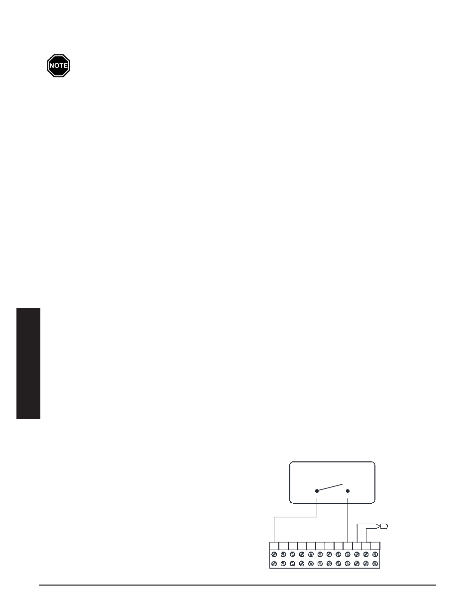
• Connect to "OS" and "SC" as shown in Figure 10.
• If the sensor wiring is routed through an external wall, the opening through which the wire is routed
MUST be sealed. Failure to do so may affect the accuracy of the outdoor temperature sensor.
• The outdoor sensor is supplied with a lead length of 40 ft. If a greater wire length is needed, it can
be extended to a total of 250 ft.
• No other loads can be controlled or supplied through this cable. It is for connection of the outdoor
sensor ONLY.
• This low voltage cable MUST not enter any line voltage enclosure.
• Unshielded Class II (thermostat) wire can be used as extension wire provided it is segregated from
any line voltage cabling.
loW voltaGe electrical connectionS - rooM
tHerMoStat (oPtional)
A low voltage (24VAC) room thermostat can be used for room temperature control with the ThermElect Hydron-
ic system. If so, Steffes recommends using a digital thermostat. To iniate a heat call, the system needs a switch
closure from R to H. This energizes the primary loop pump outputs.
12-Position Low Voltage Terminal Block Coding
R = Low Voltage Hot
C = Low Voltage Common
Y = Compressor/Stage 1 Heat Call
W = Stage 2 Heat Call
Y2 = Compressor Output
G = Fan Call
O = Reversing Valve Input
O2 = Reversing Valve Output
H = Hydronic Heat
OS = Outdoor Temperature Sensor
SC = Temperature Sensor Common
DS = Duct Temperature Sensor
installa
tion
installa
tion
T
herm
e
lecT
h
ydronic
i
nSTallaTion
3.09
i
nSTallaTion
3.08
T
herm
e
lecT
h
ydronic
LOW VOLTagE CONNECTIONS
HydRONIC HEaTINg SINgLE ZONE SySTEM
FIgURE 10
Outdoor Sensor
Hydronic Heat Thermostat, Zone
Valve, End Switch, or Pump Control
SC
H OS
W
O2
O
G
Y Y2
C
R
12 Position Terminal Block
DS