Warning, Line voltage electrical connections, Installa tion installa tion – Steffes 9180 User Manual
Page 17: 07 i, 06 t
installa
tion
installa
tion
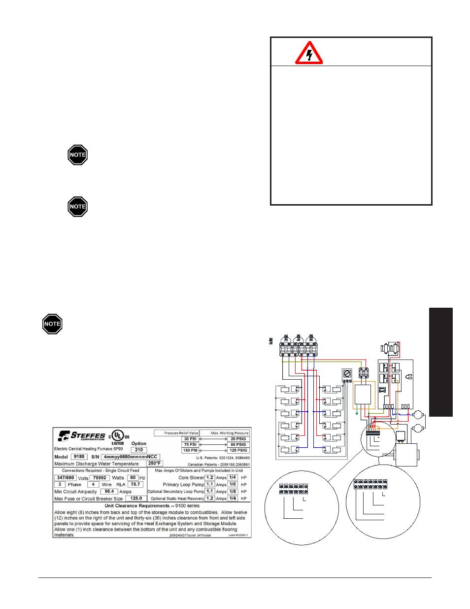
line voltaGe electrical connectionS
To determine the correct wire size required for the circuit feeding
the system, refer to the Specifications (Page A.01-A.02) and the
system's identification label located on the cover of the electrical
panel (Figure 8).
Step 1 Remove the electrical panel cover if not already removed.
Step 2 277/347 only. Mount the dry type enclosed transformer
below the electrical panel on the system's painted left
side. Use a 1/2" knockout from the bottom left side of the
electrical panel.
Install only the proper size and type fuses in
the factory supplied fuse block.
Step 3 Route all supply circuit field installed conductors through
a knockout and into the electrical panel.
Use copper or aluminum conductors rated at
75
o
C or higher for line voltage field connection
of this device.
Step 4 Make line voltage connections to lugs of single feed bus and ground lug. Refer to the Line Voltage Wiring
Diagrams (Pages A.07 - A.08) for more information on these connections.
connection of primAry loop pump
In 277/347 volt installations, a 120 or 240V single phase pump can be used. Connect the pump only to terminals
inside the electrical panel marked for connection of the primary loop pump as shown in Figure 9B.
• A 240V pump is required for 208/240V applications
(Figure 9a) as no neutral terminal is provided.
• Do not use pumps with relay outputs or electronics
• Total rating of all connected pumps cannot exceed
1.2 amps on each pump output.
• Make wiring connections according to manufac-
turer's instructions and appropriate line voltage
wiring diagram.
SaMPLE SySTEM IdENTIFICaTION LaBEL
FIgURE 8
HAZARDOUS VOLTAGE: Risk of elec-
tric shock, injury or death. Do not
energize the system until installation is
complete. Equipment MUST be installed
by a qualified technician in accordance
with all applicable local, state, national
codes and regulations.
Risk of equipment damage, personal
injury or fire. Do NOT install any wir-
ing in line voltage compartment unless
rated for line voltage. To ensure proper
operation and safety, all wiring in the
line voltage compartment MUST be
rated for line voltage.
WARNING
T
herm
e
lecT
h
ydronic
i
nSTallaTion
3.07
i
nSTallaTion
3.06
T
herm
e
lecT
h
ydronic
FIgURE 9
(277/347V Shown)
}
}
Neutral
Recovery Unit (240V)
Optional Static Heat
Secondary Pump Power
(Variable Speed)
Primary Pump
TRANSFORMERS
240v / 24v
COM
NO
COM
NO
NO
NO
1/4 Amp
COM
COM
Transformer
120/240 VAC
BASE IO BOARD
EXCHANGER
LIMITS
N.C.
AUTO
DAMPER
RESET
225 °
MANUAL
COM.
WHITE
HIGH
RESET
250°
N.C.
L2 120
L1
L2 240
BLOWER
RESISTER
L1
L2
Neutral
Power (240V)
}
Power (240V)
}
}
}
Recovery Unit (240V)
Optional Static Heat
Secondary Pump Power
(Variable Speed)
Primary Pump
Ground
4uf
Cap.
ORANGE
PRIMARY PUMP POWER
(VARIABLE SPEED)
SECONDARY PUMP POWER
OPTIONAL STATIC HEAT
RECOVERY UNIT (240V)
NEUTRAL
(240V)
}
} }
RESISTER
RED
BLUE
BLACK
5 Amp
Secondary
CORE
BLOWER
Element Relay
Neutral
#11 Right
#11 Right
Element
Element Relay
#12 Left
Ground
Lug
#12 Left
Element
Element Relay
Element Relay
Element Relay
Element
#7 Right
Element
#9 Right
#7 Right
#9 Right
#5 Right
Element Relay
Element Relay
Element Relay
#10 Left
#8 Left
#6 Left
#3 Right
Element Relay
Element
#1 Right
Element
#3 Right
#1 Right
Element Relay
#5 Right
#4 Left
Element Relay
#2 Left
Element Relay
Element
Element
#2 Left
Element
#4 Left
Element
#8 Left
#10 Left
Element
#6 Left
Element
9a - 208/240V
9B - 277347V