Caution, Brick core temperature sensor installation – Steffes 9180 User Manual
Page 16
Step 4 Lower insulation blankets back into position, one at a time. Carefully tuck the sides of the insulation into
the edges, corners, and around the exposed portions of the heating element to ensure maximum efficiency.
Use face mask, gloves, and long sleeved garments when handling insulation materials in ac-
cordance with generally accepted safety practices.
Step 5 Reinstall the galvanized front panel and secure it to the system using the screws originally removed.
Step 6 Route element harnesses through connectors, using one connector/harness until tape is centered.
Step 7 Attach element lead wires to element terminals. Start at the top using the appropriate color chart below.
Repeat pattern as necessary. The neutral white wires are jumpered together in sets of three.
277/347V = Black (Top)
208/240V = Black (Top)
240V = Black (Top)
Systems
White
3phase
Red
1phase
Red
Red
Systems
Blue
Systems Black
White
Black
Red
Blue
Red
White
Blue
Step 8 Route the orange wire to the electrical compartment. Cut the wire and crimp ends (found on orange/
black wires in electrical compartment). Connect the orange wires to the orange/black wires.
Step 9 Remove the blower access cover from the base left side. Locate the blue core blower wires and purple
(violet) water temperature sensor wires.
Step 11 Route the wires through the flanged hole at the front left corner of the base. Continue routing up to the
electrical compartment through 1/2" knockout. Connect the blue core blower wires to black and the blue
wires. Connect the two purple (violet) wires to the two purple wires..
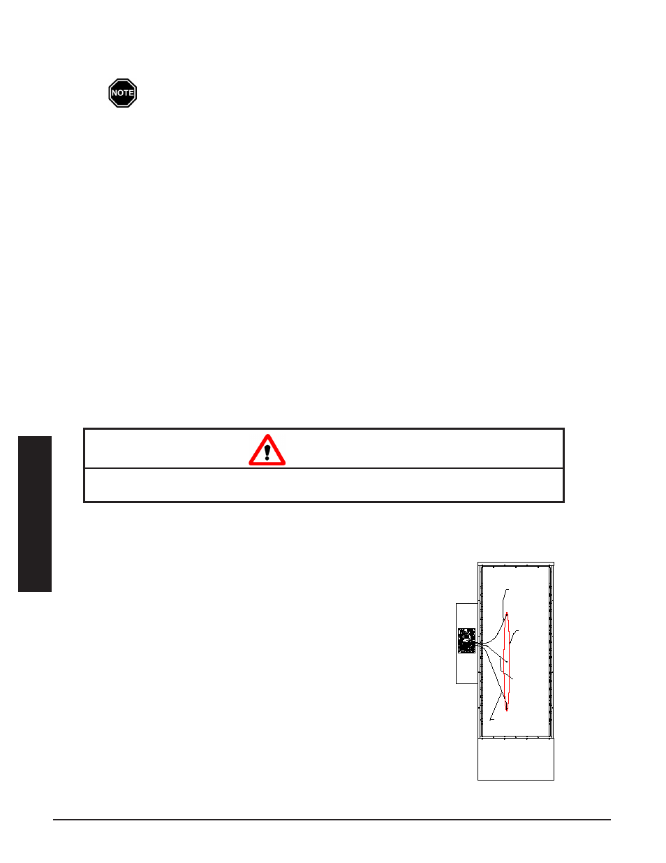
Step 1 Remove the screw(s) by the brick core temperature sensor con-
nector holes in the galvanized front panel.
Step 2 Route the brick core sensors through the 1/2" knockout up to
the relay driver board. The yellow wire from each sensor must
be connected to the Y terminal of the proper sensor connection
terminal block, and red to R. Polarity of sensors is critical.
Sensor connections MUST be installed as follows:
•
Single Module - 9150 or 9180 (Figure 7)
•
Bottom sensor to core C
•
Second sensor to core D
•
Third (if equipped) to core E
Step 3 Insert the brick core temperature sensors through the holes in
the galvanized front panel. The sensors must pass through the
blanket and board insulation and into the brick core. Use the
sensors to aid in making a passageway by rotating the sensors
while gently pushing inward.
Step 4 Once brick core sensors are installed, re-install sensor mount-
ing screws to secure and ground the sensors.
Risk of improper operation. Proper installation of the brick core temperature sensor is critical to
the operation of the heating system. Read and follow installation instructions carefully.
CAUTION
CORE TEMPERaTURE SENSOR
CONNECTIONS
FIgURE 7
Core
Temperature
Sensors
Connect To Core "E"
On 80kW Module Only
Relay
Driver
Board
Connect To
Core "D"
Connect To
Core "C"
installa
tion
installa
tion
T
herm
e
lecT
h
ydronic
i
nSTallaTion
3.07
i
nSTallaTion
3.06
T
herm
e
lecT
h
ydronic
Brick core teMPerature SenSor inStallation