Warning, Caution, Air conditioner/heat pump interface – Steffes 9180 User Manual
Page 19: Pressure relief valve installation
installa
tion
installa
tion
T
herm
e
lecT
h
ydronic
i
nSTallaTion
3.09
i
nSTallaTion
3.08
T
herm
e
lecT
h
ydronic
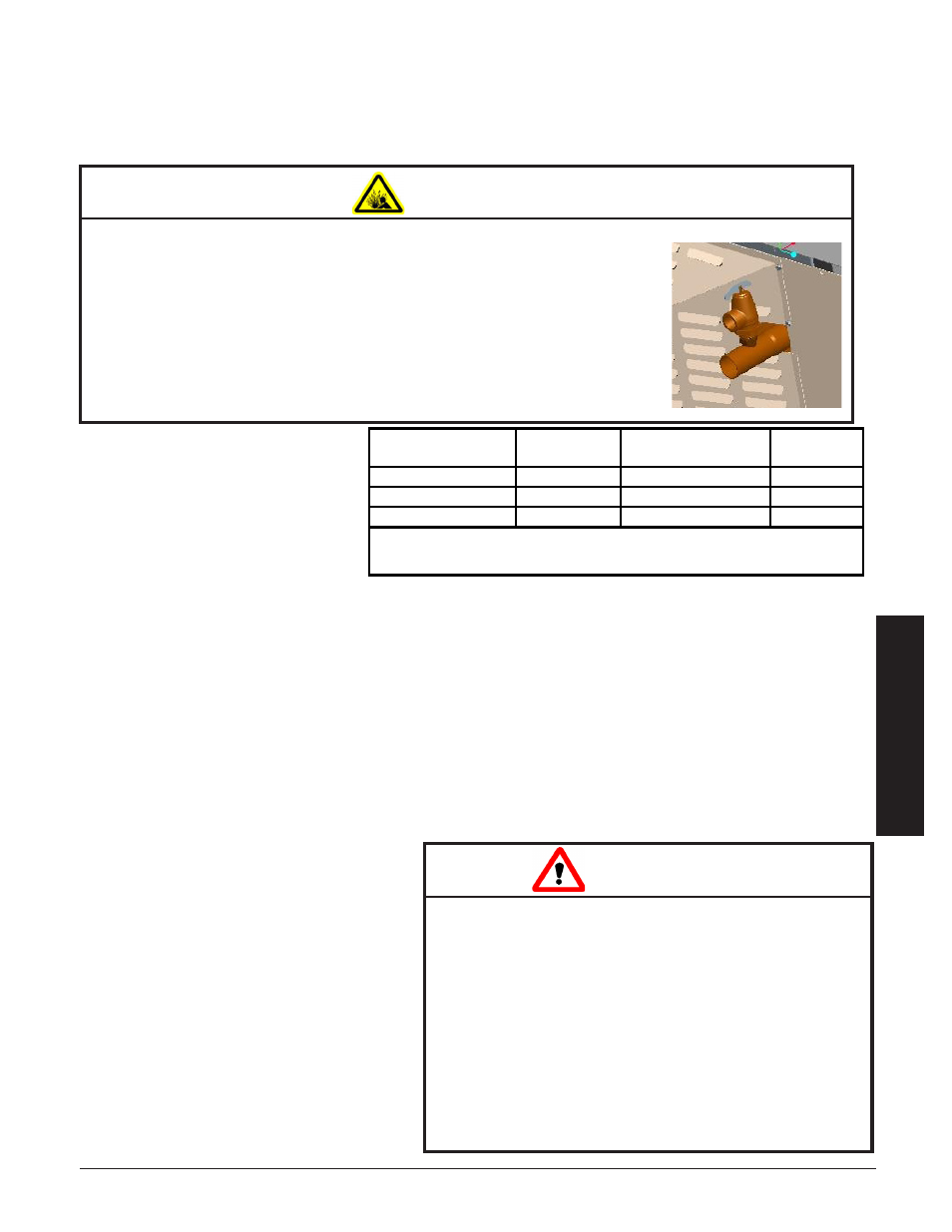
Step 1 Remove the exchanger access
panel and locate the pressure
relief valve assembly.
Step 2 Connect the pressure relief valve
to the outlet water port on the
left side of the ThermElect Hy-
dronic. It is extremely important
that the following conditions for installation of this part are met:
•
Insure all connections, including the valve inlet are clean and free from any foreign material.
•
Use pipe compound sparingly, or tape on external threads only.
•
Mount the pressure relief valve in a vertical, upright, position directly to the outlet water port of
the system. Under no circumstances should there be a flow restriction or valve of any type be-
tween the safety relief valve and the pressure vessel.
Step 3 Use schedule 40 pipe to install a discharge line for the pressure relief valve.
This discharge line MUST:
•
be connected from the valve outlet with no intervening valve and directed downward to a safe
point of discharge.
•
allow complete drainage of both the valve and the discharge line.
•
be independently supported and
securely anchored to avoid applied
stress on the valve.
•
be as short and straight as possible.
•
terminate freely to atmosphere
where any discharge is clearly vis-
ible and is at no risk of freezing.
•
terminate with a plain end that is
not threaded.
•
be constructed of a material suit-
able for exposure to temperatures
of 375
o
F or greater.
•
be, over its entire length, of a pipe
size equal to or greater than that of
the valve outlet.
air conDitioner/Heat PuMP interface
The ThermElect Hydronic system can be used in conjunction with an air conditioner or a heat pump. Contact
Steffes Corporation for more information.
PreSSure relief valve inStallation
available Pressure
Relief Valves
Minimum
BTU Rating
Maximum
Operating Pressure
Order
Item #
30 PSI
400,000
20 PSI
1100104
75 PSI
500,000
60 PSI
1100105
150 PSI
500,000
125 PSI
1100106
note: 9100 Series Systems are shipped with 75 pSi pressure relief valves.
if a different valve is required order the item number listed above.
WARNING
Risk of explosion. Can cause injury or death. The factory supplied pressure relief valve MUST be
connected to the system with the supplied fittings.
DO NOT modify this assembly.
DO NOT cap, plug, or otherwise obstruct the outlet of the pressure
relief valve.
DO mount the pressure relief valve in a vertical, upright position.
This pressure relief valve is sized to service the needs of the
ThermElect Hydronic heating system. If multiple heating systems
are being used, pressure relief valving for the other system MUST be
provided separately.
Risk of injury or property damage. During opera-
tion, the pressure relief valve may discharge large
amounts of steam and/or hot water. To reduce the
potential for bodily injury or property damage, install
a discharge line.
DO use schedule 40 pipe for the discharge line.
DO NOT use schedule 80, extra strong pipe or
connections on the discharge line.
DO NOT cap, plug, or otherwise obstruct the
discharge pipe outlet.
DO follow all local, state, and national codes
and regulations.
CAUTION