Warning, Heating element installation – Steffes 9180 User Manual
Page 15
Step 5 Locate and install the back rigid insulation inside the brick storage module. It will
be placed on top of the existing rigid insulation at the back of the module. The
angled edge will line up with the existing rigid insulation.
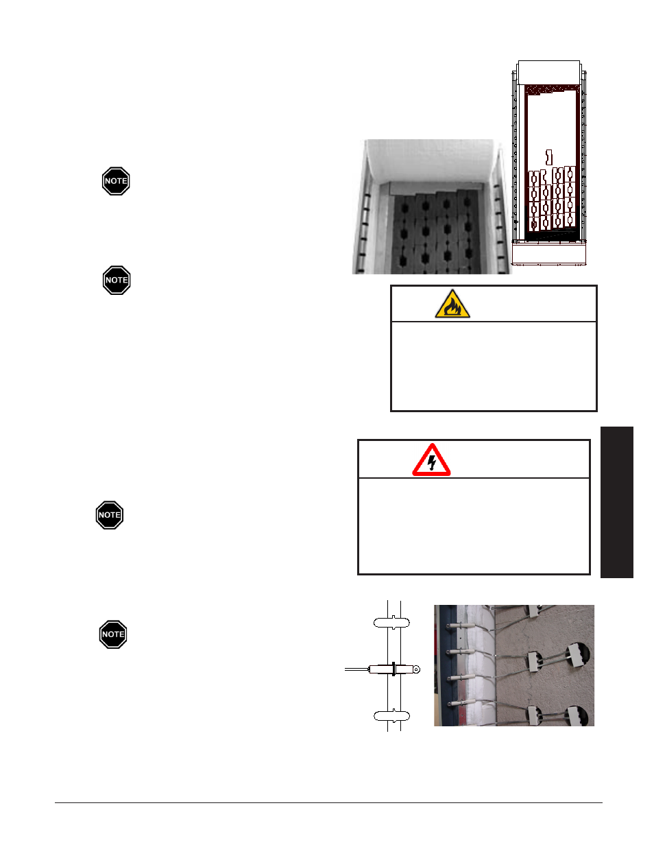
Step 6 Load the brick, one row at a time, starting at the back of the brick core and work-
ing forward. Load bricks as shown in Figure 3. Make certain brick debris does
not interfere with brick alignment front to back.
Step 7 Install top air channel block by sliding it up and
back into place on top of the bricks. (See Figure 4.)
For ease of installation, install top block
while loading bricks.
Step 8 Install the front rigid insulation (with holes) in front
of the bricks. Again, the existing angled rigid insula-
tion will line up with the front angled rigid insula-
tion.
The holes in the rigid insulation board
MUST line up with the brick openings so
elements can be installed.
installa
tion
installa
tion
HeatinG eleMent inStallation
Step 1 After all bricks are loaded and rigid insulation boards
are in place, insert the heating elements through the
insulation, sliding them in until the cement side rails
are flush with the front side of the ceramic brick.
Make sure the elements designated as "out-
er" elements are installed on the electrical
panel side of the system with the shortest
lead in the left most brick position.
Step 2 Route the element termination head with ceramic in-
sulator to the appropriate side of the system. Insert
the lead into position as shown in Figure 5.
Element leads must never cross each
other.
Step 3 Install element lead insulators. These ceramic insu-
lators MUST maintain lead wire spacings as shown
in Figure 6.
Risk of fire. Can cause personal
injury or death. DO NOT operate
the Comfort Plus Hydronic system
if damage to the insulation panels
on the inner sides of the brick core
occurs.
WARNING
FIgURE 4
HAZARDOUS VOLTAGE: Risk of electric
shock. Can cause injury or death.
DO NOT remove the electrical panel
cover while system is energized.
Elements MUST be positioned prop-
erly to avoid short circuiting against
any surfaces within the system.
WARNING
FIgURE 6
Brick inStAllAtion tipS:
•
Install bricks carefully to avoid damage to the insulation panels.
•
Remove loose brick debris to prevent uneven stacking of brick as
this can make installation of the elements and the brick core tem-
perature sensor(s) difficult.
•
Brick rows MUST line up front to back and top to bottom.
FIgURE 5
BRICK LOadINg
FIgURE 3
T
herm
e
lecT
h
ydronic
i
nSTallaTion
3.05
i
nSTallaTion
3.04
T
herm
e
lecT
h
ydronic