Cautions, Wiring diagram, White) door switch lead – Panasonic CY VMX6800U User Manual
Page 29: Room light electrical lead, Acc power lead, Ground lead, M] power socket, 2) power connector, Note
Attention! The text in this document has been recognized automatically. To view the original document, you can use the "Original mode".
g
GO
®
O
©
CO
Cautions:
oThis product is designed to operate of a 12 V DC, negative ground battery system,
o To prevent damage to the unit, be sure to follow the connection diagram below,
o Remove approximately 7/ (5 mm) of protective covering from the ends of the leads before connecting,
o Do not insert the power connector into the unit until the wiring is completed,
o Be sure to insulate any exposed wires from a possible short-circuit from the car chassis. Bundle all
cables and keep cable terminals free from touching any metal parts,
o All other installation methods require the use of dedicated metal fittings. Consult with a qualified servic
ing engineer or your dealer if other methods are required.
□ Wiring Diagram
^ J
r
-------------------- -
(Black)
—
T'
-
(Red)
(White)
Door switch lead
To the switching door trigger
Room light ground lead
Room light power lead
Room light electrical lead
Connect to the cord which was
originally connected.
Consult your nearest
professional installer.
0
Display unit
ACC power lead
To ACC power, -i-12 V DC.
Ground lead
To a clean, bare metallic part
of the car chassis.
Remote control signal
receiver lead
To the REMOTE-IN terminal
of the Panasonic DVD player
(CX-DV700U).
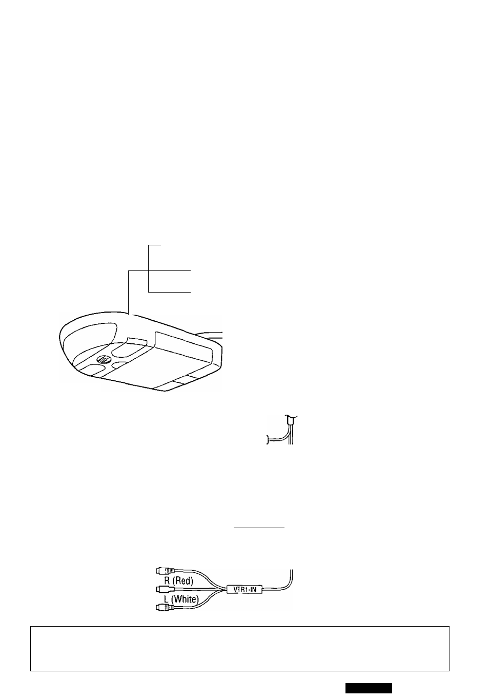
VTR1 input lead
To the audio/video output
connector of the other
device.
m] Power socket
(
2
) Power connector
Fuse 3 A
(Red)
J
(Black)
T
rémotë
-
out
M^
(Black)
Video (Yeilow)
Note:
o “REMOTE-OUT”
used for VTR1.
is exclusively
Notes:
o
Be sure to fully plug in the connector,
o
When game devices are connected, the image may be unstable.
________________ >
VMX6800U
29