Electrical connections, Wiring diagram – Panasonic CY-VM5800U User Manual
Page 21
Attention! The text in this document has been recognized automatically. To view the original document, you can use the "Original mode".
Electrical Connections
@
GO
®
\L
0
©
GO
tlS
Cautions:
• This product is designed to operate off a 12 V DC, negative ground battery system.
• To prevent damage to the unit, be sure to follow the connection diagram below.
• Remove approx. VT' (5 mm) of protective covering from the ends of the leads before connecting.
• Do not insert the power connector into the unit until the wiring is completed.
• Be sure to insulate any exposed wires from a possible short-circuit from the car chassis. Bundle all
cables and keep cable terminals free from touching any metal parts.
• Note that if your car has a driving computer or a navigation computer, disconnecting the battery cables
may cause the contents of memory for these computers to be lost.
• The parking brake connection should be connected by a professional installer. In case of difficulty,
please consult your nearest authorized Panasonic Servicenter.
• All other installation methods require the use of dedicated metal fittings. Consult with a qualified servic
ing engineer or your dealer if other methods are required.
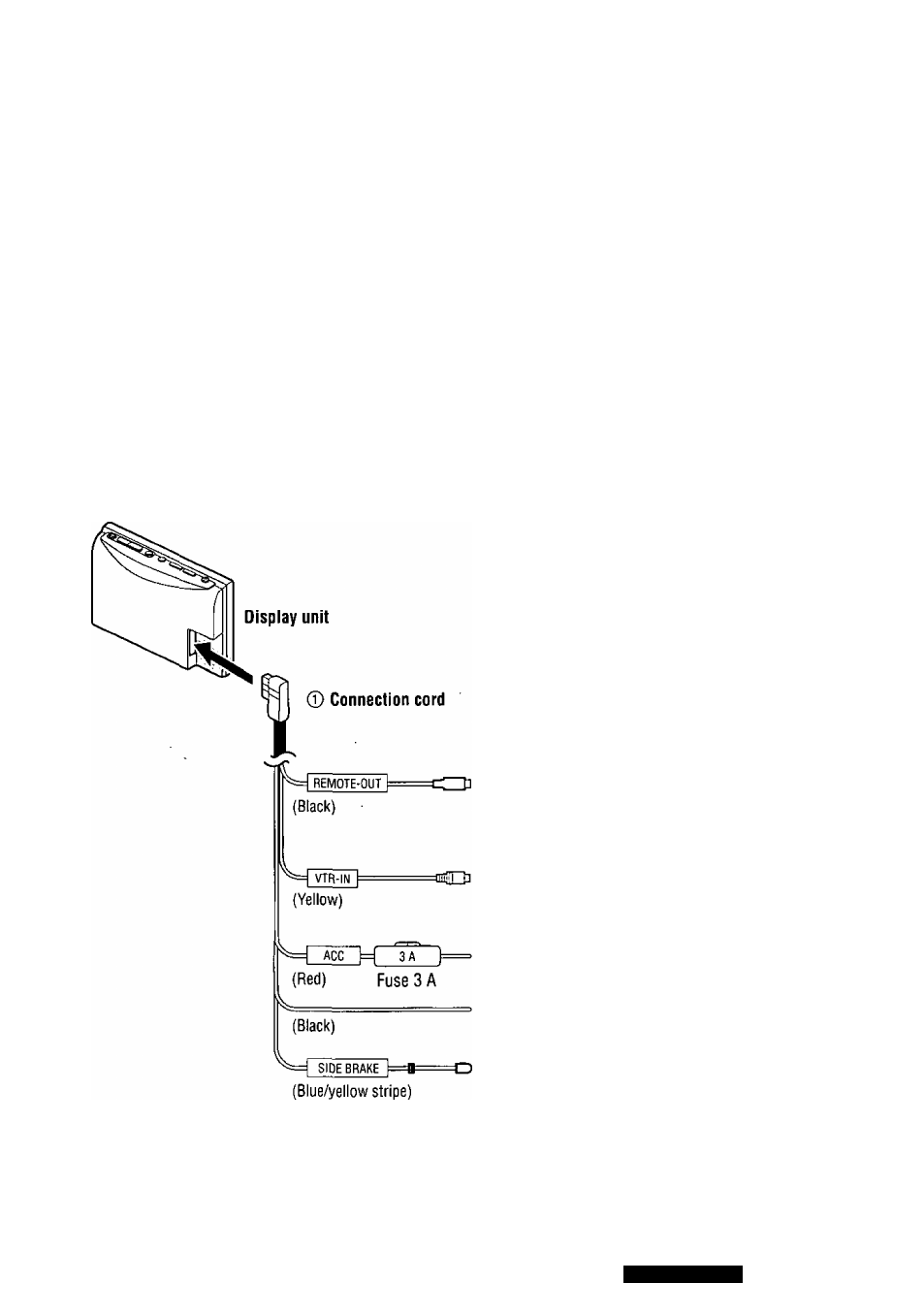
□ Wiring Diagram
Remote control signal receiver lead
To the REMOTE-IN terminal or remote
control signal receiver lead of the
Panasonic DVD player {CX-DV700U).
Video input lead
To the video output connector of the
Panasonic DVD player (CX-DV700U).
ACC power lead
To ACC power, -i-12 V DC.
Ground lead
To a clean, bare metallic part of the car chassis.
Side brake (parking brake) connection lead
Be sure to wire the side break (parking brake)
for safety and preventing accidents. page 23)
Notes:
• Be sure to fully plug in the connector.
• When game devices are connected, the image may be unstable.
C-iY£VIVI5800U
21