Assembly of the throttle linkages, Adjusting the engine control linkages, Assembly of the front shocks – OFNA Racing Jammin X1 CRT RTR User Manual
Page 20
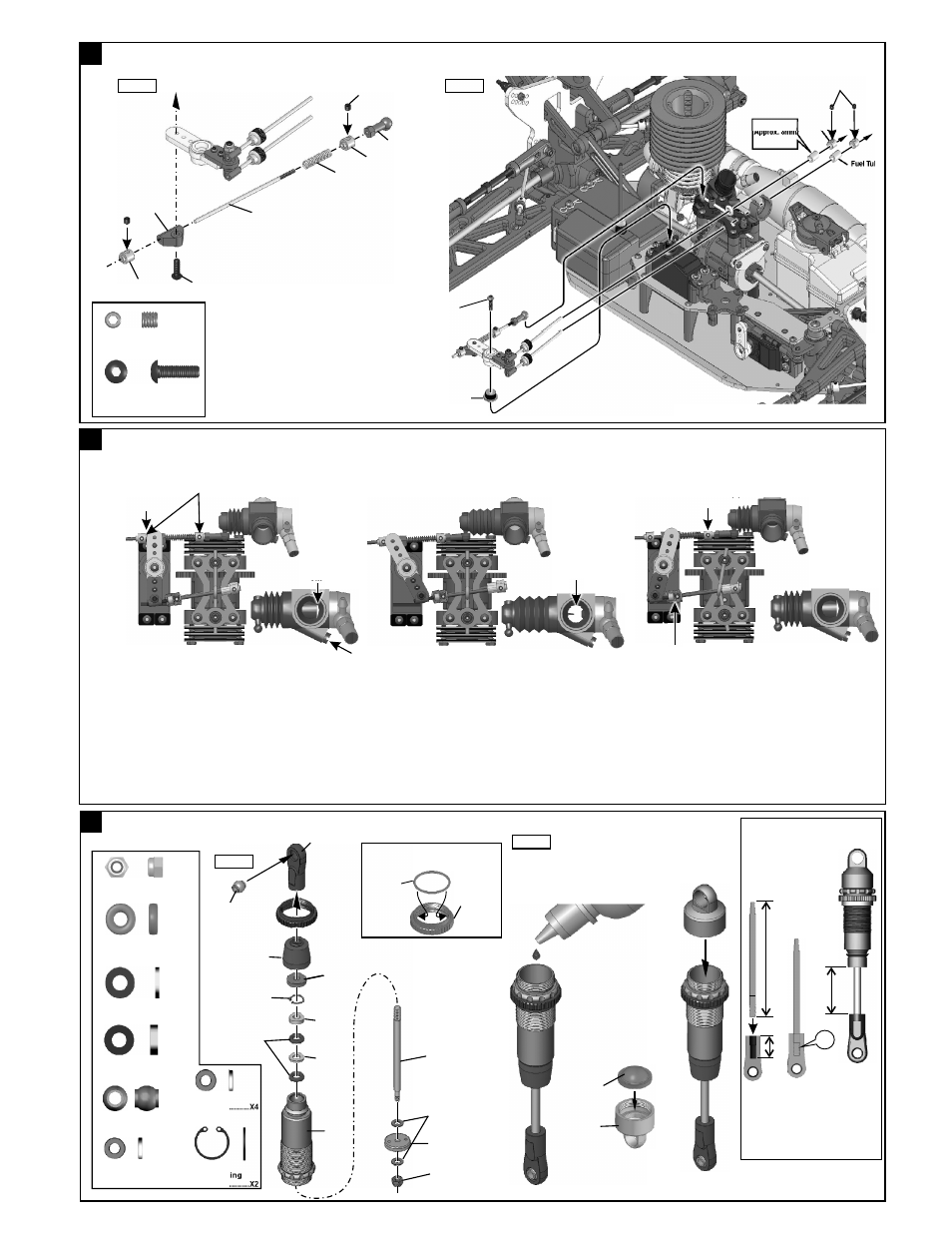
94033
3x3mm
Set Screw
Fuel Tube
10769
Servo Horn
Adapter
41
Step 1
Step 2
..........X4
94033
3x3mm
Set Screw
94033
3x3mm
Set Screw
30802
Throttle
Slider
94033
3x10mm
Hex Screw
10300
Alum
Stopper
10300
Alum
Stopper
40663
2X68mm
Rod
30531
Throttle
Spring
30802
Throttle
Ball End
ASSEMBLY OF THE THROTTLE LINKAGES
94003
3X10mm
Hex Screw
..........X1
15
94033
3x3mm
Set Screw
10300
Alum
Stopper
Fuel Tube
Approx. 8mm
* Use the screw
provided with
your servo .
42
ADJUSTING THE ENGINE CONTROL LINKAGES
Approx. 1mm gap
Carburetor is
Opening fully
10300 Alum. Stopper
10300 Alum Stopper
Approx. 0.5mm
(Neutral)
(Throttle High)
(Brake)
Turn on the Transmitter then Receiver and set the
Engine Control Servo Trim to the neutral position.
Adjust the idling adjusting screw on the Carburetor
to be open approx. 1mm gap.
Idling adjusting
Screw
Adjust both of the #158 Engine Control and Brake linkage
accordingly.
Adjust the Engine while it is not running.
Adjust the Servo-Horn mounting position for the
Carburetor to be full open.
Change the pivot mounting position on the servo
horn in case the Carburetor is not opening fully or
if it is opening excessively. Or if available on the
Transmitter, adjust the Throttle high end point.
Adjust so the brakes work smoothly.
If the brakes apply too much or not enough,
adjust 30800 accordingly. Or if available on the
Transmitter, adjust the High-End Brake
adjustment.
Adjust 30800 to Change the front or Rear Brake.
30800 Alum. Adjust Nut
.
40090
2.6x5mm
Washer
..........X2
40090
7mm C-Ring
..........X4
Step 1
* Make 2 Shocks for the front.
45
ASSEMBLY OF THE FRONT SHOCKS
40634
Spring
Adjuster
40636
15x1 O-Ring
Fit the o-ring into groove before
assembly.
..........X4
...X2
....X2
40090
2mm Washer
40090
1mm Washer
40090
3.5mm
O-Ring
40090
2.6x5mm
Washer
......X2
2.5mm Nylock Nut
....X2
40643
Shock Plastic
Ball End
(Long)
40090
7mm
C-Ring
40633
Shock Cap
40090
1mm
Washer
40090
2mm
Washer
40640
Pressure Top
40638
Shock Piston
(1.6mm x 2 )
2.5mm
Nylon Nut
2.6x5mm
Washer
40054
Shock Shaft
(Front)
Step 2
30411
6mm Ball End
*fill the shocks
with oil.
40090
3.5mm O-Ring
....X4
40632
Shock
Body
40637
Dust Felt
40635
Shock Shaft
Dust Covers
30411
6mm Ball End
OK
2
8
m
m
5
6
.7
m
m
CORRECT SHOCK ASSEMBLY
Carefully screw the shock shaft into
the bottom of the plastic ball end
untill the distance between
the ball end and the shock body is
28mm
for the front .
N.B. Do not over tighten as the plastic
will strip.
1. Pull down piston and
pour oil into the shock
cylinder.
2. To remove air bubbles
slowly move the piston
up and down.
3. Pull down piston
attach cap loosely
slowly push the
piston up almost to
the top shock oil
will overflow then
tighten cap.
* Do not overtighten
the 2.5mm nylon nut.