OFNA Racing Jammin CRT .5 Mini User Manual
Page 19
39
40
41
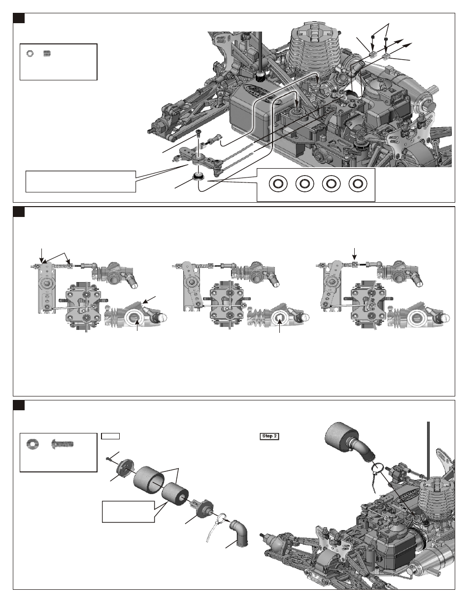
ASSEMBLY OF THE THROTTLE LINKAGES INTO LEVER
ADJUSTING THE ENGINE CONTROL LINKAGES
ASSEMBLY OF THE AIR FILTER
Step 1
Step 2
40858
40856
40857
40856
3x8mm
10185
3x3mm
10300
10300
Approx. 1mm gap
(Neutral)
(Throttle High)
(Brake)
Idling adjusting
Screw
.
10300
Approx. 0.5mm
Carburetor is Opening fully
10300
94033
3x3mm
Set Screw
.....x2
* Use the screw
provided with
your servo .
94002
3x8mm
Hex Screw
.....x1
*Apply filter oil to the
foam before use.
*Snap on.
* Choose the right servo horn adapter for your servo.
S
J
F
H
Sanwa/Airtronics
JR
Futaba
HiTech
*Ensure that servo gears are centered before attaching
the servo horns. The best way to accomplish this is by
connecting the servos to the radio system and setting
the trim to the center.
Turn on the Transmitter then Receiver and set the
Engine Control Servo Trim to the neutral position.
Adjust the idling adjusting screw on the Carburetor
to be open approx. 1mm gap.
Adjust both of the 10300 Engine Control and Brake
linkage Accordingly.
Adjust the Engine while it is not running.
Adjust the Servo-Horn mounting position for the
Carburetor to be full open.
Change the pivot mounting position on the servo
horn in case the Carburetor is not open fully or
if it opening excessively. Or if available on the
Transmitter, adjust the Throttle high end point.
Adjust 10300 so the brakes work smoothly.
If the brakes apply too much or not enough,
adjust 36140 accordingly. Or if available on
the adjustment.
Adjust 36140 to change the front or rear brake.