Ecb 62 base, Hw manual-3 – Rane ECS v2 Hardware (ECB 6 and ECM 8) User Manual
Page 3
HW Manual-3
ECB 62 BASE
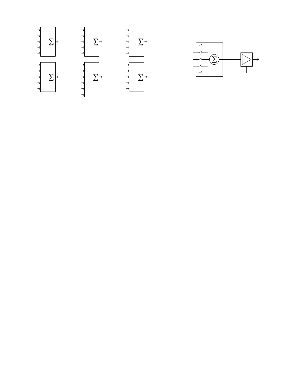
Figure 2. ECB 62 Audio Bridge
Figure 3. Port 1 Selection and Control
THE BASE
The ECB 62 Base is the master controller of the ECM 82
Mixers. The Base consists of a six port audio bridge, with an
optional internal ECS 62 Stereo Expansion module. The Base
can be used by itself as a six-by-six Port line-level audio
mixer and router. Bridging bases together creates more Ports.
All functionality is controlled through RaneWare. Soft-
ware controls are printed in
bold san-serif type like this. See
the RaneWare Operators Manual for complete details.
AUDIO BRIDGE
The audio bridge allows the connection of six full-duplex
audio devices—thus the term six Port audio bridge. See
Figure 2 above. Each Input Port has both a hardware 10 dB
PAD switch on the front panel and software programmable
Input Attenuation controls. Each Output Port, except Port 5,
consists of a program selectable five input
Audio Mixer/
Router and programmable Output Attenuation controls, as
shown in Figure 3. Port 5 has a program selectable six input
Audio Mixer/Router. This type of configuration for Ports 1-4
and 6 prevents the connection of an Input to its Output,
avoiding a possible feedback condition.
PORT 1
The Port 1 Input is different from all other Ports. This Port
contains a six input line summer, connecting up to six Mixers.
All mics in the room are connected to this Port through the
ECM 82 Mixers. This Port contains a six input line mixer,
connecting up to six ECM 82 Mixers. See Figure 3.
The Output of Port 1 is also different from all other Ports.
It is designated as the Program Port, delivering audio to the
room sound system. It has both a balanced Right channel and
a summed Mono Output of Right and Left. An installed ECS
62 Stereo Expansion Module delivers the balanced Left
channel. The Mono Output connects to the Echo Canceller
Reference on all ECM 82 Mixers.
STATUS SIGNALS
The top center of the ECS software screen (and the ECB
62 front panel) contains the following Status indicators – all
of which can be obtained via RS-232 based room control
devices. (In the ECB 62 Device Control Language of the
RaneWare Operators Manual-29 refer to the RW 232 Com-
mand Get OPSTAT.)
The three Signal indicators – Program, Port and Mic – are
used within ECS to identify the current audio state of the
system, i.e., where audio is present or absent. The patented
performance advantages and much of ECS’s automatic
functionality is derived from the system being aware of these
indicators’ current state.
Program Signal indicator (PGS LED on the ECB 62)
The Program indicator lights whenever audio is detected
at the Port 1 (Program) Output, thus indicating that audio
should be heard in the room. (If
P3 Prog Contribute on the
System tab is checked, both Port 1 and Port 3 Outputs are
used to “sense” Program audio.
Port Signal indicator (PTS LED on the ECB 62)
The Port indicator lights whenever audio is detected at
any Port Input whose
Signal Mode is set to Automatic. This
includes mixer audio entering Port 1.
Mic Signal indicator (MCS LED on the ECB 62)
This lights whenever audio is detected at any Active Mic
whose
Mic Mode is set to Automatic.
Advanced auto power down example: Use the room
controller to monitor the Port and Mic Signal indicators.
When either is present, reset the power down timer that
eventually shuts down the system thus saving the projector
bulb, the associated power bill and actually save money!
Master Port
Identifies the current
Master Port, which is the Port that
most recently detected audio. Use
Master Port Delay on the
System tab for multipoint video applications.
Master Mic
Identifies the current
Master Mic, which is the Mic that
most recently detected audio. A Master Mic is a status signal
generated when audio is detected at a Mic Input for a period
of time longer than the Master Mic Delay timer setting. If an
Input is assigned as Last On, and audio is detected for a
period longer than the Master Mic Delay timer, that Input
becomes the Master and remains on until a new Input takes
over. The old Master Mic then releases and returns to its set
Gate Depth. Use
Master Mic Delay on the System tab for
video-follows-audio applications.
PORT 6 (PHONE)
PORT 2 (CODEC)
PORT 3 (AUX 1)
PORT 4 (AUX 2)
PORT 5 (VCR)
data
OUTPUT
LEVEL
INPUT
SELECTS
OUTPUT
ATTENUATION &
OUTPUT BUTTON
PROGRAM OUT
OFF = MUTE
PORT 1
1
2
3
4
5
PORT 6
PORT 2
PORT 3
PORT 4
PORT 5
PORT 1
1
2
3
4
5
PORT 6
PORT 1
PORT 3
PORT 4
PORT 5
PORT 2
1
2
3
4
5
PORT 6
PORT 1
PORT 2
PORT 4
PORT 5
PORT 3
1
2
3
4
5
PORT 6
PORT 1
PORT 2
PORT 3
PORT 5
PORT 4
OUT
OUT
OUT
OUT
OUT
OUT
1
2
3
4
5
6
PORT 6
PORT 5
PORT 1
PORT 2
PORT 3
PORT 4
PORT 5
1
2
3
4
5
PORT 5
PORT 1
PORT 2
PORT 3
PORT 4
PORT 6