Eca 1 echo canceller module, Hw manual-10 – Rane ECS v2 Hardware (ECB 6 and ECM 8) User Manual
Page 10
HW Manual-10
Warning: Proper static discharge measures must be
followed when installing or configuring this card.
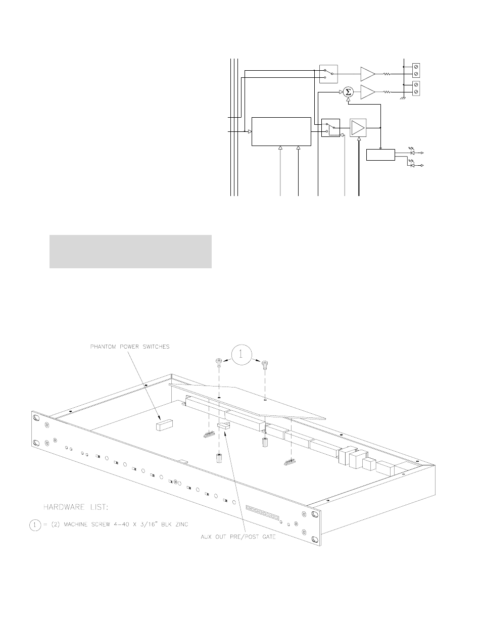
Figure 11. ECA 1 Installation with ECM 82 Phantom Power and network termination jumper locations
AUX
ECHO CANCELLER
ECA 1 MODULE
TRANSMIT
IN
TRANSMIT
CTRL.
MIX
OUTPUT LED
DRIVER
+5V
+5V
SIGNAL
OL
E/C BYPASS
and
Suppressor
MIX
POST-GATE
PRE-GATE
OUT
OUT
CTRL.
Mixer Gate
INTERNAL
SELECT
OPTIONAL
IN
OUT
RECEIVE
301
301
-10dBu
-14dBu
Figure 10. ECA 1 Block Diagram (detail from Data Sheet Block Diagram).
ECA 1 ECHO CANCELLER MODULE
DESCRIPTION
The ECA 1 is a continually adaptive acoustic Echo
Canceller module for the ECM 82 Mixer using DSP technol-
ogy. Each ECM 82 Mixer allows the addition of an internal
acoustic Echo Canceller. Placing the Echo Canceller in each
Mixer reduces the number of acoustical echo paths for a
multi-microphone system, thereby improving the audio
quality of the system. This method of echo cancelling is
called MZEC™ MultiZone Echo Cancelling. See page HW
Manual-7.
Since the Echo Canceller automatically adapts to the
room, training is not required.
The ECA 1 installs by temporarily removing the top cover
of the ECM 82 and seating the module onto factory installed
standoffs on the motherboard.
After installing the Echo Canceller, disable
Echo Cancel-
ler Bypass in RaneWare (see the RaneWare Operators
Manual).