Hit Products Logic 3 User Manual
Page 7
Do not use pre-filled wire nut connectors as they will impede the transfer
of the signal through the wire splice.
TEST BEFORE BACK-FILLING TRENCH.
To easily test for communication and wire integrity, connect each receiver to the
field wiring at each planned location. It is not necessary for receiver to be
attached to solenoid/valve for test, but O.K. if already connected. Do not allow
black receiver wires to touch each other (short or ground) when testing.
Manually sequence controller through each station number for minimum of 30
seconds, checking each activated receiver in the field for a continuously
activated bright LED light on each receiver. A continuously activated bright LED
light on receiver during station activation confirms satisfactory communication.
Modular Surge Protection Board
The surge protection board is attached directly underneath the large main
controller printed circuit board. This board and its components are like a
sophisticated fuse. It will blow in an attempt to save the main circuit board from
destruction by line surges mainly created by lightning. It is connected to the main
board with a simple plug for easy removal for testing and replacement if
necessary.
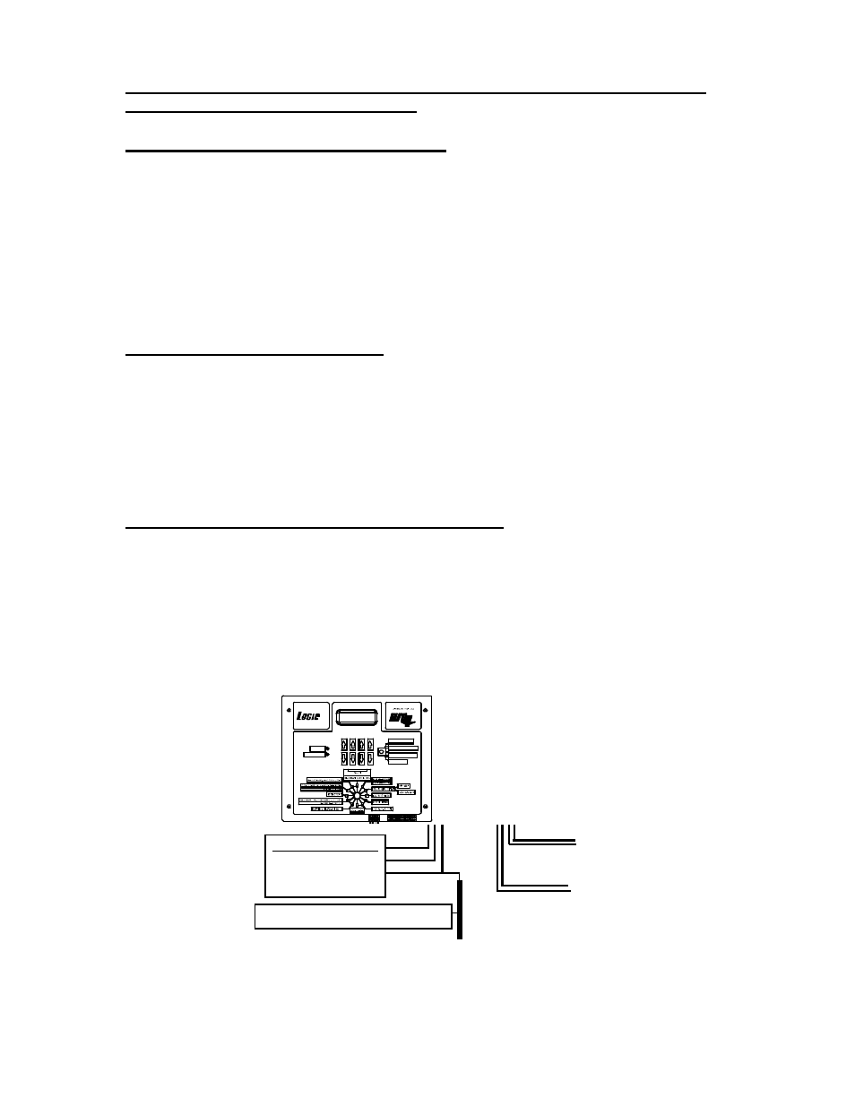
LOGIC 2 and LOGIC 3 Internal Surge Protection
The terminal connectors for the field and ground wires located on the internal
surge protection board will accept up to 10 gage wire allowing the field wiring to
be directly connected. Access is made by removing the stainless steel panel
held by two screws directly below the face plate. Note : Make sure all wiring
connectors are tight and it is recommended to use only soldered connections or
dry-type DBC waterproof connectors for all main 2-wire splices.
CALENDAR ODD / EVEN
PRE WET / FERTIGATION
MASTER CLEAR
PROGRAM RECEIVER
FERTIGATION ON
MASTER ON
BLACK
WHITE
GREEN
10
´
GROUND ROD -Keep ground moist.
?
?
?
?
GFI CIRCUIT 110 VAC
THIS CONNECTION
SHOULD BE MADE BY A
QUALIFIED TECHNICIAN
.
RED LINE 1
RED LINE 1
BLUE LINE 2
BLUE LINE 2
5