Hit Products Logic 3 User Manual
Page 17
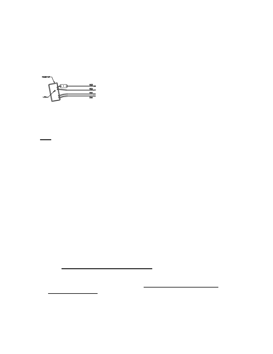
Programmable Receiver Number Identification Tags
Hit Products has developed a user friendly, flexible means to identify the number
of the field-programmed receivers during the receiver programming process.
Inside every box of programmable receivers, you will find one set of identification
tags numbered 1-128. You will use these receiver identification tags as follows:
1. Every time a receiver is programmed, find the corresponding numbered identification
tag and immediately attach to receiver.
2. To attach identification tag to receiver, insert one red receiver wire into the hole (from
front to back) to the left of the appropriate numbered tag as you are looking at the
number. Pull red wire all the way through the hole until identification tag is
approximately one inch from body of receiver.
Note: This will leave the engraved number unobstructed by the wire.
3. Insert same end of same red wire back through hole (from back of tag towards front)
and continue to pull wire through until tight. The number on the tag should now be
readily visible and the black wire positioned on back (blank side of tag). See above.
4. Should receiver ever be reprogrammed to a different number, make sure to replace the
identification tag with the appropriately numbered identification tag. Failure to do so can
create extreme confusion!
Installation “Do’s & Don’ts” with Logic 2 Wire Controllers
1. Proper wire sizing is a must. Use Ohm’s law for determining proper 2 wire run wire
size. See instruction booklet.
2. Each 2-wire run must be a continuous run, no tees, no branches, and no loops. Each
2-wire run must have one beginning (at the controller terminal) and one end only (at
the last valve).
3. Logic receivers must be directly attached to the 2-wire run; red to field wires, black
to solenoid.
4. All wire connections must be waterproof, using “dry type” wire connectors (DBC
Series by Hit Products or DBY/DBR Series™, 3M™) and/or soldered and then
installed in waterproof housings.
*****Do not use pre - filled gel type wire nuts.*****
5. Do not install Logic Controller, its receivers or any Logic field wire within 15 ft. of
any high voltage electrical panels, meters, pumps, equipment or controls.
6. Use with standard 24 VAC solenoids only. Do not use with low power/diode
bridge type solenoids.
7. Use different colored wires for each wire in each 2 wire run.
8. “Line 1” is one pair of wires for a 2 wire run. “Line 2” is the second two wire run.
Do not mix “Line 1” and “Line 2”. This controller is a computer, install it accordingly
and it will serve you well. If you have any questions, please don’t hesitate to call the
factory at (800) 468-0071, ext. 331 for help, 8am-5pm, Mon-Fri.
15