Installing the cable-management system, Step 1, Step 2 – Cisco 10720 User Manual
Page 9: Step 3, Figure 4 attaching cable-management tray step 4, Step 5
9
Installing the Cable-Management System
78-13101-02
Installing the Cable-Management System
•
Power cables and power supplies have been checked for compatibility with your power service.
•
Labels on the equipment have been checked to ensure that the power service at your site is suitable
for the Cisco 10720 Internet Router.
•
AC- or DC-power source voltage receptacles are easy to reach.
Installing the Cable-Management System
Perform the following steps to install the cable-management system:
Step 1
Power down your router. (Refer to Chapter 5, “Maintaining the Cisco 10720 Internet Router”, in the
Cisco 10720 Internet Router Installation and Configuration Guide.)
Step 2
Attach an ESD-preventive wrist strap to your wrist and to the router; or to a bare metal surface. (See
“Preventing Electrostatic Discharge” section on page 4
.)
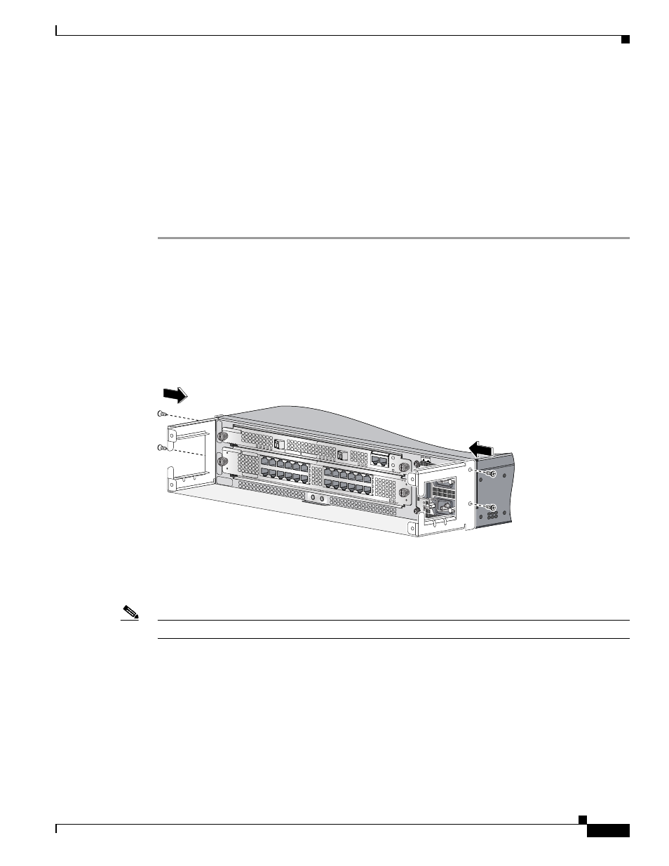
Step 3
Attach the cable-management tray to the router using four of the 3.5 mm x 6 mm screws that are shipped
with the router. Secure the cable-management tray by two screws on each side of the router chassis. (See
.)
Figure 4
Attaching Cable-Management Tray
Step 4
Connect all interface cables to their respective ports if necessary.
Step 5
Separate the interface cables and lead them out the sides of the cable-management tray. Use cable ties
to keep the cables together. (See
.)
Note
To avoid damage to the cables, avoid excessive bending.
AC OK
DC OK
OTF
AC OK
DC OK
OTF
INPUT 100-2
00- 50/60Hz 2
-5A
DON NOT R
EMOVE
OR INSERT C
ABLES
WITH THE P
OWER ON
CA
RD
F
AIL
CARD FAIL
LINK/ACTIVE (G)
100 MBPS
PO
W
ER
RESET
CONSOLE
AUX
OV
ER
TE
M
P
AC
TIV
E
CA
RD
F
AIL
SY
STE
M
S
TAU
S
PO
W
ER
CA
RR
IE
R
RX
P
KT
W
RA
P
PA
SS
T
HR
U
66296