Wall mounting the router, Posts. (see, Figure 12 – Cisco 10720 User Manual
Page 14
14
Wall Mounting the Router
78-13101-02
Rack Mounting the Router
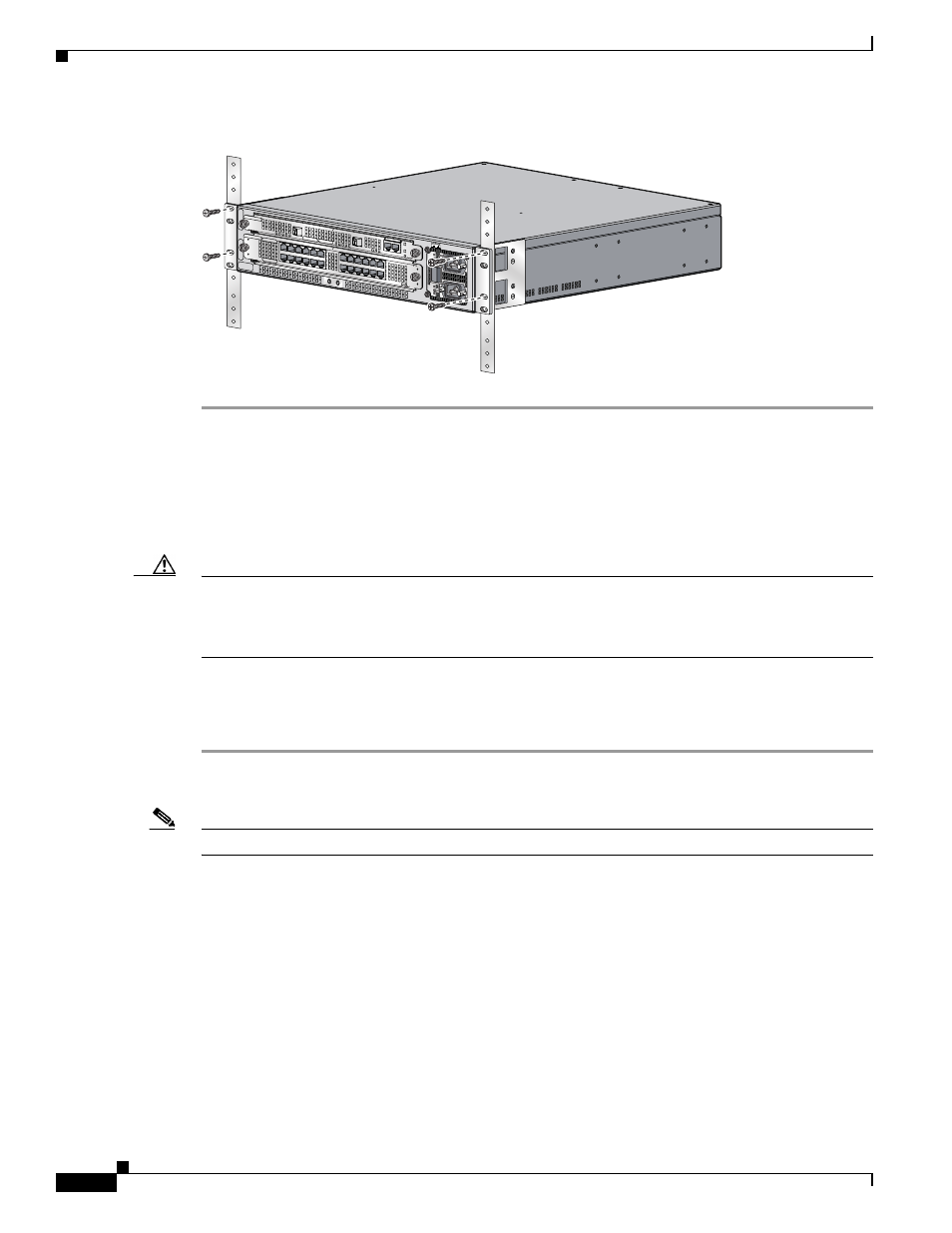
Figure 12
Attaching the Router to the 19-Inch Rack (Front Panel Forward)
Wall Mounting the Router
The wall mount brackets must be mounted on a minimum 5/8” (15.9 mm) wallboard gypsum or
equivalent with twelve 1 1/4” No. 10 screws or equivalent (M5 x 31.8 mm).
Caution
The front and back panels of the Cisco 10720 Internet Router require at least 6 inches clearance away
from the wall or other items that can block proper air flow. The side panel requires 1 inch clearance away
from the wall or other items that can block proper air flow. The top and bottom of the router chassis do
not require any specific clearance.
The following steps illustrate hot to set up a proper and secure wall mount for the router. These steps
ensure adequate ventilation is available at all times. A Number 1 Phillips screwdriver is required to
perform the following procedure:
Step 1
Locate the two 17.25-inch (43.82) long metal mounts; twelve 1 1/4-inch No. 10 (3.18 cm) screws, and
ten screws for attaching the mount to the router chassis, included in the accessories kit.
Note
Verify that no electrical, heating, or plumbing should be located behind the drilling location.
Step 2
Predrill 12 holes on the mounting surface. The holes on the side of the router chassis are 3.23 inches (8.2
cm) apart. The side to side distance is 18.35 inches (46.6 cm). (See
.)
AC OK
DC OK
OTF
AC OK
DC OK
OTF
INPUT 100-200- 50/60Hz 2-5A
DON NOT REMOVE
OR INSERT CABLES
WITH THE
POWER ON
CARD FAIL
CA
RD
F
AI
L
LIN
K/
AC
TI
VE
(G
)
10
0
M
BP
S
POWER
RESET
CONSOLE
AUX
OVERTEM
P
ACTIVE
CARD FAIL
SYSTEM
STAUS
POWER
CARRIER
RX PKT
WRAPPASS THRU
57665