Removing the cable-management system, Step 1, Step 2 – Cisco 10720 User Manual
Page 11: Step 3, Step 4, Step 5, Figure 9 removing the cable-management tray, Card fail link/active (g) 100 mbps
11
Removing the Cable-Management System
78-13101-02
Removing the Cable-Management System
Removing the Cable-Management System
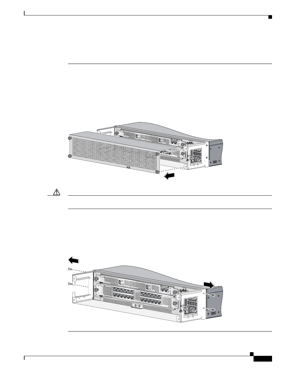
Perform the following steps to remove the cable-management system:
Step 1
Attach an ESD-preventive wrist strap to your wrist and to the router; or to a bare metal surface. (See the
“Preventing Electrostatic Discharge” section on page 4
.)
Step 2
Verify that all cables are safely secured before detaching the cable-management cover. If the
cable-management cover is not installed go to Step 5.
Step 3
Remove the cable-management cover from the router by removing the four screws that secure the
cable-management cover to the router. (See
Figure 8
Removing the Cable-Management Cover
Caution
To avoid accidental damage to router cables or card ports, it is recommended that all cables are removed
before removing the cable-management tray.
Step 4
Remove cable ties and separate the interface cables if needed to lead the cables into the inside of the
cable-management tray. (See
.)
Step 5
Detach the cable-management tray from the router by removing the two 3.5mm x 6mm screws on each
side of the router. (See
Figure 9
Removing the Cable-Management Tray
AC OK
DC OK
OTF
AC OK
DC OK
OTF
INPUT 100-200- 50/60Hz 2-5A
DON NOT REMOVE
OR INSERT CABLES
WITH THE POW
ER ON
CARD FA
IL
CARD FAIL
LINK/ACTIVE (G)
100 MBPS
PO
WE
R
RESET
CONSOLE
AUX
OVE
RTE
M
P
ACTIVE
CARD FAIL
SYST
EM
STAUS
PO
WER
CARRIER
RX PKT
WR
AP
PASS THRU
66299
CISCO 10720 INTERNET R
OUTER
AC OK
DC OK
OTF
AC OK
DC OK
OTF
INPUT 100-200- 50/60Hz 2-5A
DON NOT R
EMOVE
OR INSERT C
ABLES
WITH THE P
OWER ON
CARD FAIL
CA
RD
F
AIL
LIN
K/A
CT
IV
E (G
)
10
0 M
BP
S
POWER
RESET
CONSO
LE AUX
OVERTEMP
ACTIVE
CARD FAIL
SYSTEM STAUS
POWER
CARRIER
RX PKT
WRAPPASS THRU
66297