Step 8, Figure 7 installing the cable-management cover, Ca rd f ail lin k/a ctiv e (g ) 100 m bp s – Cisco 10720 User Manual
Page 10: Card fail link/active (g) 100 mbps
10
Installing the Cable-Management System
78-13101-02
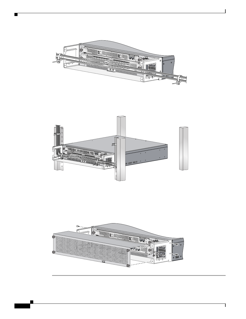
Installing the Cable-Management System
Figure 5
Managing Router Cables with the Cable-Management Tray
Step 6
Use cable ties to secure the cables to the rack to keep the wires from accidental bends or breaks. (See
Figure 6
Cable-Management Installed in the Rack
Step 7
Power up the router. (Refer to Chapter 5, “Maintaining the Cisco 10720 Internet Router”, in the
Cisco 10720 Internet Router Installation and Configuration Guide.)
Step 8
(Optional) Using a Number 1 Phillips screwdriver, attach the cable-management cover with four screws
that secure the cable-management cover to the router. (See
.)
Figure 7
Installing the Cable-Management Cover
AC OK
DC OK
OTF
AC OK
DC OK
OTF
INPUT 100-2
00- 50/60Hz
2-5A
DON NOT REMOVE
OR INSERT CABLES
WITH THE POWER ON
CARD FAIL
CA
RD
F
AIL
LIN
K/A
CTIV
E (G
)
100 M
BP
S
POWER
RESET
CONSOLE
AUX
OVERTEMP
ACTIVE
CARD FAIL
SYSTEM STAUS
POWER
CARRIER
RX PKT
WRAPPASS THRU
57749
57844
AC OK
DC OK
OTF
AC OK
DC OK
OTF
INPUT 100-2
00- 50/60Hz 2
-5A
DON NOT R
EMOVE
OR INSERT C
ABLES
WITH THE P
OWER ON
CA
RD
F
AIL
CA
RD
F
AI
L
LI
NK
/A
CT
IV
E
(G
)
10
0
M
BP
S
PO
W
ER
RESET
CONSOLE
AUX
OV
ER
TE
M
P
AC
TIV
E
CA
RD
F
AIL
SY
ST
EM
S
TA
US
PO
W
ER
CA
RR
IE
R
RX
P
KT
W
RA
P
PA
SS
T
HR
U
AC OK
DC OK
OTF
AC OK
DC OK
OTF
INPUT 100-200- 50/60Hz 2-5A
DON NOT REM
OVE
OR INSERT CABLES
WITH THE POW
ER ON
CAR
D FAIL
CARD FAIL
LINK/ACTIVE (G)
100 MBPS
POW
ER
RESET
CONSOLE
AUX
OVERTEM
P
ACTIVE
CARD FAIL
SYSTEM
STA
US
PO
WER
CARR
IER
RX PKT
W
RAP
PASS THRU
57748
CISCO 10720 INTERNET R
OUTER