Basic connections, Interface board – Welch Allyn Poem NIBP Module DeveloperS Kit Instructions - Installation Guide User Manual
Page 2
POEM NIBP Module Developer’s Kit Instructions
Welch Allyn OEM Technologies
Page 2
Confidential
810-1209-01 Rev. A
Basic Connections
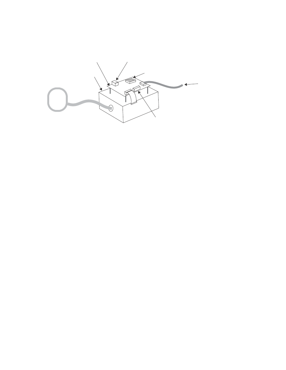
The basic connections of the POEM NIBP Module Developer’s Kit are shown below.
Figure 1 - POEM NIBP Module Developer’s Kit
After connection, the NIBP Module is controlled from the PC using the POEM PC or POEM Talk
software program. The developer has access to all POEM Module operating modes and patient
modes.
If desired, the Developer’s Kit may be partially or totally connected to the host’s target system for
convenience in developing code in the host system. The Interface Board’s power supply inputs or
logic-level serial interface may be directly connected to the host target system.
Interface Board
All electrical connections to the POEM Module are made through the Interface Board mounted
on the top of the Interface Box. The Interface Board provides:
•
Two possible power connections (only one used at a time):
• J1: 5-contact terminal strip to connect to HOST_5V, HOST_3.3V, VBUS, and GND
• J2: Barrel-style power input connector which permits powering the POEM Module
from a single, regulated or non-regulated, dc-output power adapter (or from a single
regulated dc supply)
•
5V linear regulator (used only with power adapter input)
•
F1: Fuse in series with VBUS
•
P1: Jumpers to configure the polarity for the power adapter input
•
D3: Power indicator LED lights whenever 5 V power is present
•
S1: Reset switch; pressing S1 resets the POEM Module
•
J4: A 0.1-inch grid pad arrangement for either soldering wires to or adding a
connector for access to all Module connections
•
RS232 level translators for RXD and TXD
•
J6: A female DB9 connector for direct connection to a PC’s serial port
•
J5: A 1x6 connector for coupling ECG_SYNC from the host system.
NIBP HOSE
NIBP CUFF (OR
SIMULATOR)
CABLE TO PC
(WITH POEM PC OR
POEM TALK SOFTWARE
INSTALLED)
POWER CONNECTOR (FOR POWER ADAPTER OR “BARREL
CONNECTOR PIGTAIL CABLE)
POEM MODULE INTERFACE BOX
(WITH POEM MODULE INSIDE)
INTERFACE BOARD
POWER CONNECTIONS
(FOR REGULATED EXTERNAL POWER SUPPLY)
CONNECTION FOR OPTIONAL ECG
SYNCHRONIZATION (REQUIRED FOR SMARTCUF)