Tjernlund SS2 SideShot (Discontinued Version - Pre UC1 Universal Control) 8504063 Rev B 11/99 User Manual
Page 7
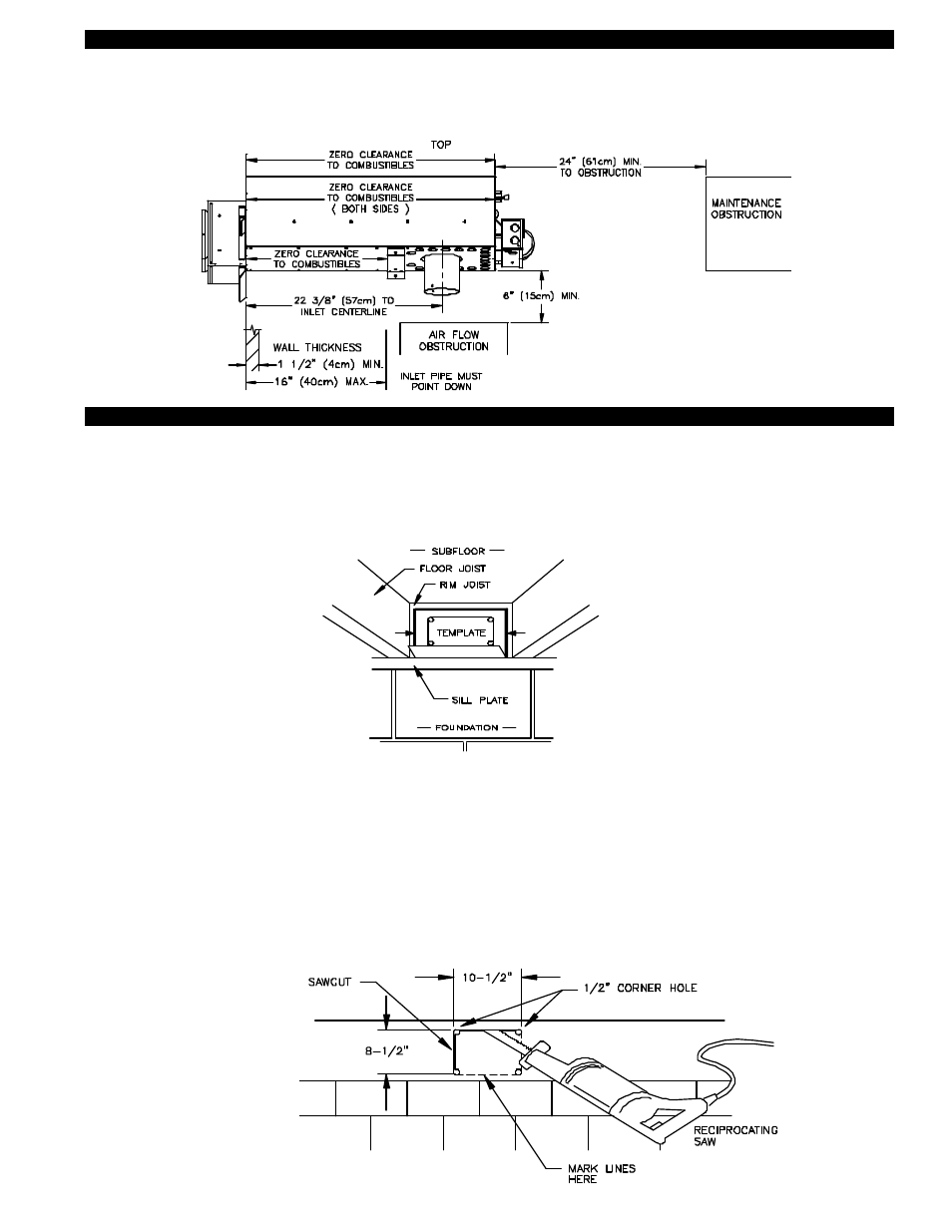
6
SS2 VENT SYSTEM CLEARANCES FROM COMBUSTIBLES & OBSTRUCTIONS
With an inlet flue gas temperature of 650oF (343oC) or below, the SS2 has been Listed for Zero Clearance from combustibles.
NOTE: You must allow a minimum 2 foot distance of unobstructed clearance behind the SS2 Vent System for doing
maintenance. Allow 6” minimum clearance from bottom of vent cabinet to any obstruction for air flow.
DIAGRAM B
2. Verify that wall penetration will not come in contact with concealed wiring or plumbing. Using 1/2” bit, drill pilot holes noted on
each side of the template from inside through rim-joist, wall board, siding, etc., keeping drill bit perpendicular to the wall. 1/2" bit
must be long enough to penetrate through exterior.
3. Remove template from rim-joist and attach to building exterior, aligning pilot hole markings on template with holes previously
created in Step #2.
4. Drill remaining (4) corner holes noted on the template through the building exterior. Remove the template and mark lines from
the outside edge of the holes drilled, forming a rectangle.
5. Using reciprocating saw and appropriate blade, cut a rectangular opening through the rim joist, wall board, siding, etc., on the
lines marked in step 4. The rectangular opening should be no larger than 10-1/2" in width by 8-1/2" in height, (See Diagram C).
6. Knock out block material exposing rectangular opening through the wall.
DIAGRAM C
INSTALLING SS2 VENT CABINET
1. a) Fold SS2 Vent Cabinet template (Page 18) along dashed line and attach between the floor joists ensuring that it is snug
against the sill plate and centered between the floor joists. Follow same procedure if floor trusses are used, (See Diagram B).
b) If the SS2 is not being installed between floor joists, attach the template to the wall it will be exiting ensuring it is level.