Tjernlund SS1C SideShot (Discontinued Version - Pre UC1 Universal Control) 8504040 Rev 4 05/95 User Manual
Page 9
b)
If installing the bracket into a masonry wall, drill 2 holes at each point established in step 3 with a 1/4" masonry drill bit
approximately 1" deep. Tap the masonry anchors into the holes drilled in step 4. Screw the wall bracket onto the wall.
5. Connect the other end of wall support bracket to the stud on the plenum using the supplied 1/4"-20 keps nut. (See Diagram J).
INSTALLATION OF VENT PIPE
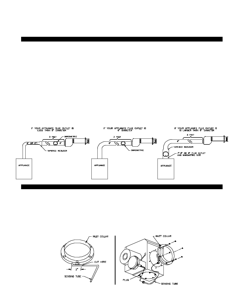
A barometric draft control must be used for the SideShot installation. Install the barometric draft control as shown, (See Diagram
K). The SideShot Vent System is designed to accept all brands of 6" single wall, Class "A" or Type "L" vent pipe. Type “B” is not
suitable for the SideShot. The vent pipe used must be in compliance with local codes and the listing of the vent pipe manufac-
turer. When necessary, install tapered reducers and increasers as shown below.
Determine which inlet of the SideShot Vent System will allow for the least amount of elbows to the appliance. DO NOT USE
BOTH INLETS. Calculate the equivalent vent pipe meters (feet) from the appliance to the SideShot Vent System by adding the
straight vent pipe length and the equivalent elbow lengths together. Each 90 degree elbow is equal to 3.1 meters (10 feet) of
straight vent pipe, each 45 degree elbow is equal to 1.5 meters (5 feet) of straight pipe. The equivalent vent pipe length must not
exceed 15.2 meters (50 feet) from the appliance to the SideShot Vent System. Vent runs of over 4.5 linear meters (15 linear feet)
should use an approved, insulated vent connector to prevent problems related to sulfur condensation. It is not necessary to main-
tain a 1/4" rise per every .30 meter (1 foot) of horizontal when Side Wall Venting.
The SideShot Vent System is shipped from the factory with the plug connected to the rear and the vent pipe inlet collar connected
to the bottom. If using the bottom inlet, skip to the section entitled "Vent Pipe Clamp Assembly". If your installation requires the
use of the rear inlet, follow the steps in the section entitled "Vent Pipe Inlet Collar Conversion" to move the vent pipe inlet collar
from the bottom to the rear.
VENT PIPE INLET COLLAR CONVERSION
1. Remove the plug from rear inlet port by unfastening the 6 nuts that secure it to the Plenum. Keep the plug & nuts for later use.
2. Remove the sensing tube from the Fan Proving Switch by loosening the plastic compression fitting.
3. Remove the vent pipe inlet collar from the bottom port by unfastening the 6 nuts. Keep the nuts for later use.
4. Using a tube cutter, cut the sensing tube 2" from the elbow directed at the vent pipe inlet collar, (See Diagram L). Discard
the cut off section of metal tube.
8
DIAGRAM K
DIAGRAM L
DIAGRAM M