Tjernlund SS1C SideShot (Discontinued Version - Pre UC1 Universal Control) 8504040 Rev 4 05/95 User Manual
Page 14
13
DRAFT ADJUSTMENT OIL
The SideShot Vent system will properly vent a wide range of BTU/hr. input capacities. To compensate for different burner capaci-
ties, vent connector lengths and wind conditions it features a draft adjustment located on the outside of the Vent Hood. In general,
positioning the draft adjustment inward will cause the SideShot to operate at lowest capacity. Positioning the draft adjustment
outward will cause the SideShot to operate at highest capacity.
IMPORTANT:
The following paragraph describes the initial draft adjustment. It may be necessary to make a slight readjustment to compensate
for various conditions: wind, vent connector resistance, negative building pressure and multiple appliances.
ASHRAE lists the average design factor for wind loads in North America at 15 MPH. Refer to the Draft Adjustment Chart on Page
14. We recommend that the 25 MPH category be used to allow for excursions beyond the 15 MPH average. It is not recom-
mended for the SideShot to be terminated on a wall that faces the direction of prevailing winds. Backdrafts by severe winds can
cause oil odors to remain in the structure and/or interrupt heating equipment operation. If the SideShot is terminated in a direction
prone to higher winds, or if higher winds are common in your geographic area, use the 40 MPH category to determine the proper
draft adjustment setting. If the draft adjustment is set at the 25 MPH category and sustained winds exceeding 25 MPH are pre-
sent, the Fan Proving Switch will disrupt the burner until the wind load drops below 25 MPH. Wind loads referenced are based on
straight line winds directed against the Vent Hood.
DRAFT ADJUSTMENT PROCEDURE:
1) Set the draft adjustment to the appropriate setting based on the above instructions and the Draft Adjustment Chart. Adjustment
is accomplished by loosening both nuts on each side of the Vent Hood and centering both indicators to the desired setting.
The four nuts should be finger tight plus 1/2 turn.
2) Place the appliance and SideShot in operation. Measure the over-fire draft. Make necessary adjustments to the primary air
intake and barometric draft control to comply with the over-fire draft requirements of the appliance. In most cases, the over-fire
draft should be in a range of -.02" to -.04" W.C. If adjustments to the primary air intake and barometric draft control do not
provide the required over-fire draft, the SideShot draft adjustment must be repositioned, accordingly. Measure over-fire draft
after repositioning SideShot draft adjustment.
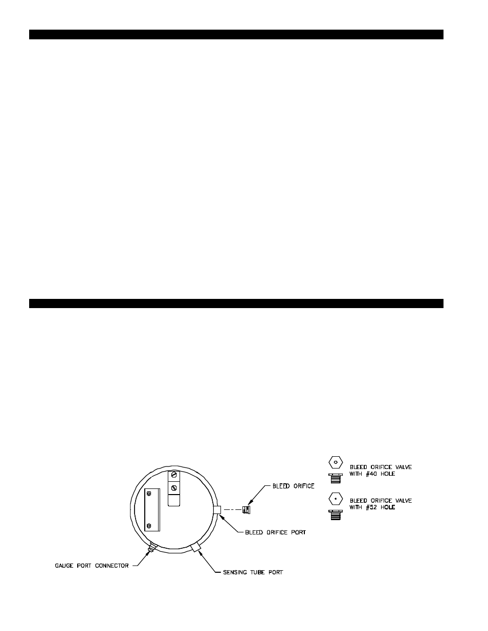
SELECTION OF PRESSURE SWITCH BLEED ORIFICE
In order for the SideShot pressure switch to function properly for the intended application, the proper bleed orifice has to be
selected as determined below.
1. Upon installation, if the vent connector length is less than 3.1 equivalent meters (10 feet), then the smaller
opening #52 bleed orifice should be used.
2. Upon installation, if the vent connector length is greater than 3.1 equivalent meter (10 feet), then the larger
opening #40 bleed orifice should be used .
3. Once proper bleed orifice has been determined, install into the Bleed Orifice port as indicated.
DIAGRAM P