Tjernlund SS1C SideShot (Discontinued Version - Pre UC1 Universal Control) 8504040 Rev 4 05/95 User Manual
Page 10
5. Attach the vent pipe inlet collar to the rear inlet port making sure that the sensing tube is orientated as shown, (See Diagram M,
Page 8). NOTE: Alignment marks on the inlet collar and plenum casing must match.
6. Attach 90o compression fitting to the short tube on the inlet collar.
7. Using the "soft" aluminum tubing, connect the Fan Proving Switch to the inlet collar. Take care not to crimp the tubing.
8. Install the plug removed in step 1 over the bottom inlet port, tightening securely.
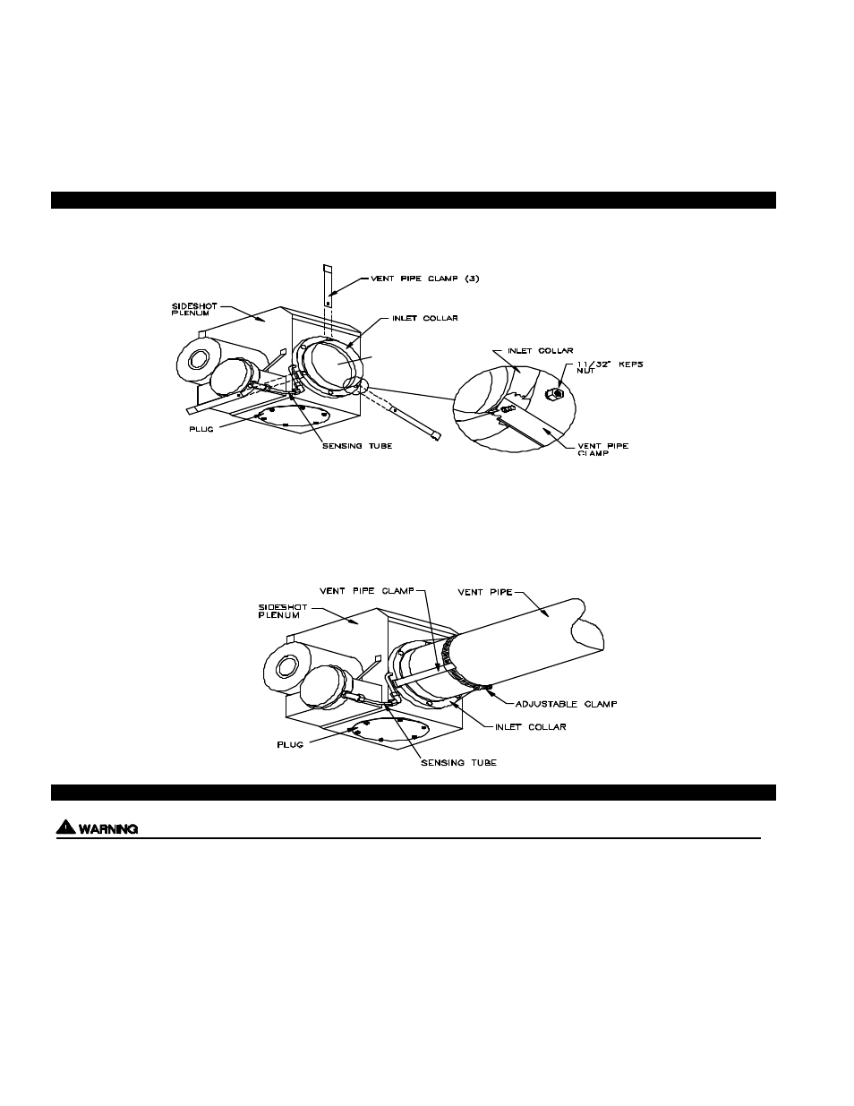
VENT PIPE CLAMP ASSEMBLY
1. Attach the three vent pipe clamps to the inlet collar, (See Diagram N).
NOTE: The following diagrams show the use of the rear inlet. The same steps will apply if using the bottom inlet.
2. Bend each vent pipe clamp so it conforms to the outside diameter of the vent pipe being used, (See Diagram O)
3. Route the adjustable clamp through the openings at the opposite end of the legs.
4. Slide the vent pipe over the inlet collar of the SideShot.
5. Tighten the adjustable clamp around the vent pipe, (See Diagram O).
ELECTRICAL WIRING OIL
The electrical supply to the SideShot shall be supplied from the appliance. All wiring from the SideShot to the appliance must be
appropriate Class 1 wiring as follows: installed in rigid metal conduit, intermediate metal conduit, rigid non-metallic conduit,
electrical metallic tubing, Type MI Cable, Type MC Cable, or be otherwise suitably protected from physical damage.
The electrical contact ratings for the diaphragm Fan Proving Switch and High Limit are as follows:
FAN PROVING SWITCH
HIGH LIMIT
6.2 Amps (full load) at 120 VAC
10 Amps (full load) at 120 VAC
36 Amps (locked rotor) at 120 VAC
60 Amps (locked rotor) at 120 VAC
The Fan Proving Switch and High Limit are not suitable for loads which exceed the above limits.
9
DIAGRAM N
DIAGRAM O