Tjernlund SS1C SideShot (Discontinued Version - Pre UC1 Universal Control) 8504040 Rev 4 05/95 User Manual
Page 11
10
SEQUENCE OF OPERATION WITH SIDESHOT INSTALLED ON OIL FIRED APPLIANCES:
As the thermostat/aquastat senses a need for heat, the internal switch of the thermostat/aquastat will close. The switch closure
sends current through the internal controls of appliance (e.g. high limit, low limit and all other safety controls the appliance is
equipped with) and continues through the R8184G primary control. Current will then flow out of the orange of the R8184G to the
SideShot Relay/Timer and safety circuit. When the Relay/Timer receives current, the SideShot motor is energized. After draft is
established within the SideShot, the Fan Proving Switch closes completing the circuit to the burner motor. It is important to
remember that the electrical interlock of the SideShot is always done at the final signal which would normally start the burner
motor. All thermostats, zones, limits and circulators are to be wired as normally done on a chimney vented appliance.
All diagrams in this section show the same electrical connections. Follow the diagram which is most appropriate for your installation.
If your appliance is not equipped with an R8184G as outlined in these diagrams, locate the wire from the primary control which is
connected to the black burner motor wire and follow the steps outlined on Page 11.
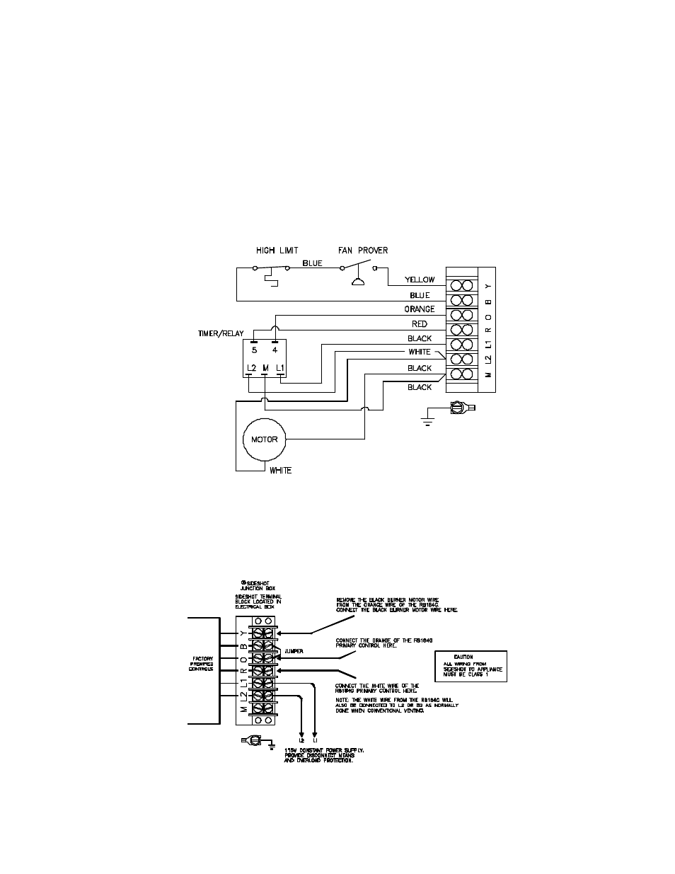
SIDESHOT FACTORY WIRING
TYPICAL OIL FIELD WIRING