7 core module dip switches, 8 core module reset procedure, 9 the power supply – Rice Lake Tracer AVi - v2.0 User Manual
Page 8: 10 fuse replacement, 11 interface cables
4
Tracer AVi
Installation Manual
Communications Cable Distance Limitations
The maximum cable lengths that can be used for
various communications types depend on a number of
factors. These include: output impedance of the
transmitter; electrical noise in the environment; cable
capacitance, gauge, termination, and shielding.
Given that these and other factors will affect the
maximum usable cable length, the following distances
c a n b e u s e d a s a g e n e r a l g u i d e f o r
i Q u b e
communications cabling (10 ft cable is provided):
RS-232:
50 ft (15 m)
2.7
Core Module DIP Switches
The DIP switches on the
iQube
core module must be
set to configure the
iQube
as a primary or secondary
unit, and to specify the type of serial communications
provided by the unit. Table 2-3 lists the DIP switches
and their functions.
2.8
Core Module Reset Procedure
If
VIRTUi
does not recognize the connection to the
load cell, the core module may need to be reset to
initialize the
iQube
firmware.
To reload the default firmware into the
iQube
core
module, do the following:
1. Power-off the
iQube
. Remotely powered units
can be powered off by temporarily removing
fuse F1 (see Figure 2-2 on page 3).
2. Set core module DIP switch 8 ON.
3. Power-on the
iQube
.
4. Power-off the
iQube
.
5. Set DIP switch 8 OFF.
6.
Power-on the
iQube
. The reset is now complete.
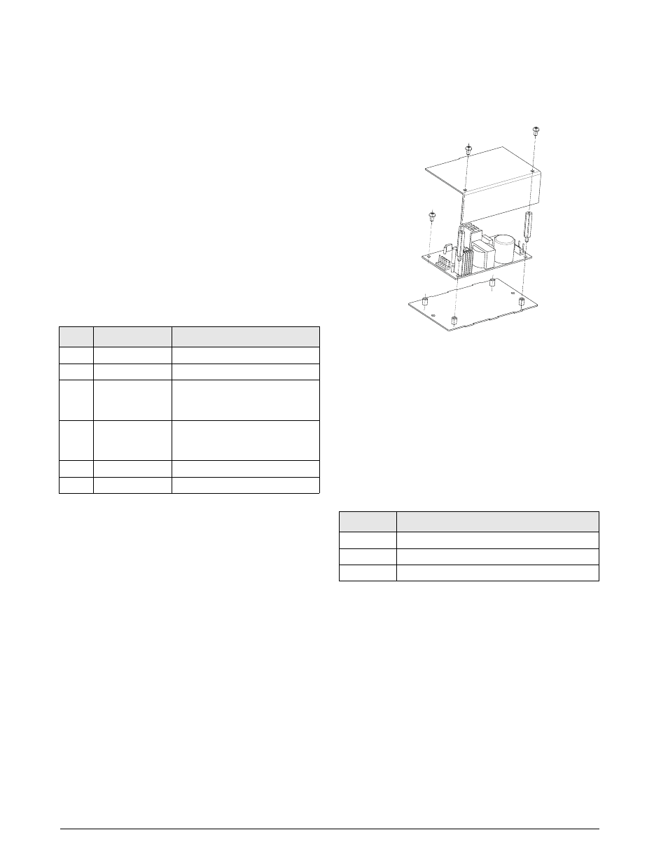
2.9
The Power Supply
The internal power supply provides 100-240 VAC,
50-60Hz, Output 7.5 VDC.
Figure 2-3. iQube 7.5V Power Supply
2.10 Fuse Replacement
Fuse F1 on the
iQube
connector board (see Figure 2-2
on page 3) provides protection for power supplied to
the connector board and core module at connector J5.
F u s e F 1 i s p o l y r e s e t t a b l e a n d d oe s n o t n e e d
replacement. See Section 6.0 on page 17 for complete
fuse specifications.
2.11 Interface Cables
Table 2-4 lists the cables for the
iQube
.
Switch
Function
Values
1–3
Primary
OFF, OFF, OFF = PRIMARY
4
Setup enable
ON = setup enabled
5
Host
communication
protocol
OFF = RS-232
6
Host
communication
port
OFF = Port J7
7
Reserved
OFF
8
Load default
OFF
Table 2-3. Core Module DIP Switch Settings
PN
Description
50749
Cable for com port to PC
72704
RS-232/USB connector
93563
Cable for remote display
Table 2-4. iQube Cables