0 installation, 1 unpacking and assembly, 2 enclosure security/disassembly – Rice Lake Tracer AVi - v2.0 User Manual
Page 6: 3 mounting the iqube and remote display, 4 cable connections, 5 load cells, Installation
2
Tracer AVi
Installation Manual
2.0
Installation
This section describes procedures for connecting load
cell, power, and serial communications cables to the
iQube
TM
enclosure.
Drawings and replacement parts
lists are included for the service technician.
Use a wrist strap to ground yourself and
protect components from electrostatic
discharge (ESD) when working inside the
iQube
enclosure.
Disconnect AC power from the main module before installing
remote displays.
2.1
Unpacking and Assembly
Immediately after unpacking, visually inspect the
contents to ensure all components are included and
undamaged. The shipping carton should contain the
iQube
, the remote display, and connection cables. If
any parts were damaged in shipment, notify Rice Lake
Weighing Systems and the shipper immediately.
See Table 2-4 on page 4 for information on the
iQube
cables.
2.2
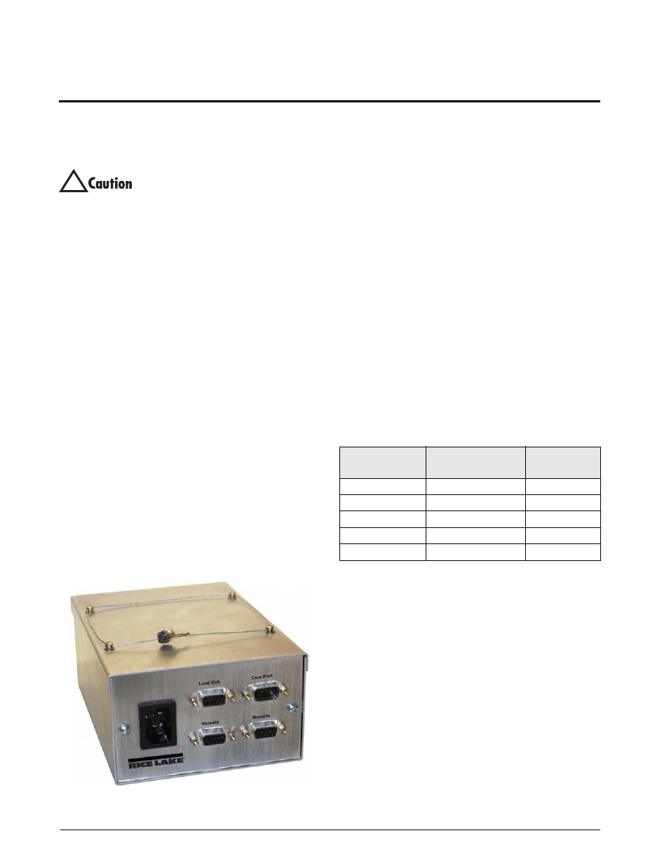
Enclosure Security/Disassembly
After an NTEP inspector has examined the unit, he/
she will install security cables pictured in Figure 2-1.
These cables prevent the
Tracer AVi
from being
tampered with by an unauthorized individual. If these
cables are removed, NTEP certification will become
void.
If the
Tracer AVi
enclosure must be opened by an
authorized technician, ensure power is disconnected,
then place it on an anti-static work mat. Cut the
tamper-proof cables, remove screws, and remove the
enclosure’s cover. An NTEP inspector will have to
examine the unit and attach new security cables.
Figure 2-1. Security cables installed
2.3
Mounting the iQube and Remote
Display
The
iQube
and remote display are two separate
components. The main board is installed in the
iQube
.
All components can be installed in separate locations.
The
iQube
can be placed either upright or on its side.
Mounting hardware is not included in the parts kit.
2.4
Cable Connections
The single channel
iQube
provides one load cell
connector, two remote display connectors, one host
(PC) com port connector for connecting to the PC
running
VIRTUi
, and an AC power cord.
2.5
Load Cells
The load cell wired to connector J3 in the
iQube
, is
assigned a default name A1. J3 is wired to a DB-9 on
the enclosure panel.
Load Cell Wiring
To attach the load cell cable to the connector board,
plug the cable into external connector (see Figure 2-6
on page 6).
Wire load cell cables as shown in Table 2-1.
!
DB-9 Pin
Female Connector
On-Board Connector
(J3)
Function
7
1
+SIG
3
2
–SIG
4
3
+EXC
6
4
–EXC
5
5
SHIELD
Table 2-1. Load Cell Connector Pin Assignments