0 adjustments and calibration, 1 mechanical adjustments, 2 corner correction – Rice Lake RoughDeck BDP with Portability Option User Manual
Page 13: Adjustments and calibration, 1 mechanical adjustments 5.2 corner correction
RoughDeck BDP Installation/Operation Manual
9
5.0
Adjustments and Calibration
The following sections describe adjustments that need to be made to the RoughDeck BDP barrel scale.
5.1
Mechanical Adjustments
To accommodate minor floor unevenness, the scale feet can be used to adjust scale height up or down a fraction
of an inch. Adjust the feet by hand or with a screw driver until all feet are contacting the floor equally. No jam
nuts are supplied for locking the feet, as there is a slight decrease in accuracy when jam nuts are tightened.
However, if you feel that your application requires you to secure the feet, we suggest using Teflon
®
1
tape or
Loctite
®
2
.
When adjusting scale feet, use care to prevent the scale foot from bottoming out against the underside of the load
cell. Also, the foot stem can be damaged by bending or stripping threads if extended beyond the maximum height
adjustment.
When height adjustments are complete, recheck the bubble level located in the center of the deck. The scale deck
must be level within 1/4 inch.
5.2
Corner Correction
All assembled RoughDeck BPD scales are corner-trimmed at the factory as part of the final assembly process.
Corner trimming is only necessary after replacing a load cell.
To calibrate the scale, the output from each load cell must be matched by adjusting the signals with
potentiometers in the junction box—a process known as trimming.
Remove the junction box cover and identify the correct load cell terminal corresponding to each corner (labeled
CELL 1, CELL 2, and so on). See Figure 6-4 on page 13 for scale deck corner numbering.
The indicator must be connected and calibrated approximately, but it need not indicate the exact weight value. A
test weight is required. The recommended test weight for all RoughDeck BDP models is 25% of scale capacity;
for example, 250 lbs for 1K-lb models, 650 lbs for 2.5K-Lb models.
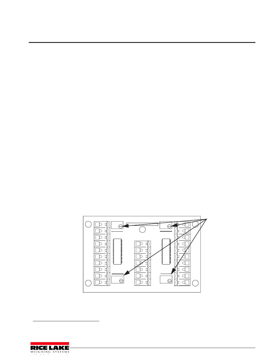
With no weight on the scale, zero the indicator. Then turn all four potentiometers (Figure 5-1) clockwise to
increase the reading until a clicking sound is heard from each potentiometer. This ensures the maximum signal
from each load cell.
Figure 5-1. Summing Board Diagram
1. Teflon® is a registered trademarks of E.I. DuPont.
2. Loctite® is a registered trademarks of E.I. DuPont.
CELL 1
CELL 4
CELL 2
CELL 3
INDICA T OR
+EX
–EX
+SI
–SI
100 K
+SE
–SE
+EX
+EX
+EX
+EX
–EX
–EX
–EX
–EX
+SI
+SI
+SI
+SI
–SI
–SI
–SI
–SI
SHD
SHD
SHD
SHD
23126
Rev. A
SHD
JU1
JU2
JU3
JU4
100 K
100 K
100 K
Potentiometers