Figure 3-3. junction box wiring diagram, Figure 3-4. load cell protection, Figure 3-5. junction box diagram – Rice Lake RoughDeck BDP with Portability Option User Manual
Page 10: Floor load cell cable steel cover, 6roughdeck bdp installation/operation manual
6
RoughDeck BDP Installation/Operation Manual
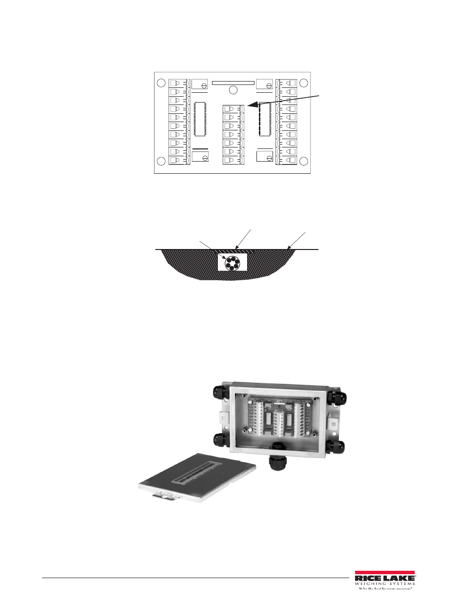
Figure 3-3. Junction Box Wiring Diagram
For permanent installations it’s desirable to have the cable routed to the indicator in a manner that will protect the
cable from damage. This method of cable protection in non-washdown applications is shown in Figure 3-4.
Figure 3-4. Load Cell Protection
7. When the interface cable is protected and in its final position, complete connections to the indicator. See
the indicator installation manual for wiring information.
8. If necessary, trim corners as described in Section 5.2 on page 9.
9. Check all strain relief fittings for tightness.
10. Put the cover back onto the junction box assembly and place the junction box back in the scale.
11. Secure the scale junction box cover plate.
Figure 3-5. Junction Box Diagram
CELL 1
CELL 4
CELL 2
CELL 3
INDICA T OR
+EX
–EX
+SI
–SI
100 K
+SE
–SE
+EX
+EX
+EX
+EX
–EX
–EX
–EX
–EX
+SI
+SI
+SI
+SI
–SI
–SI
–SI
–SI
SHD
SHD
SHD
SHD
23126
Rev. A
SHD
JU1
JU2
JU3
JU4
100 K
100 K
100 K
I n d i c a t o r t e r m i n a l
location
FLOOR
LOAD CELL CABLE
STEEL COVER