Rice Lake RL1200 Portable Beam Scale User Manual
Page 27
Final Adjustment, Calibration and Troubleshooting
23
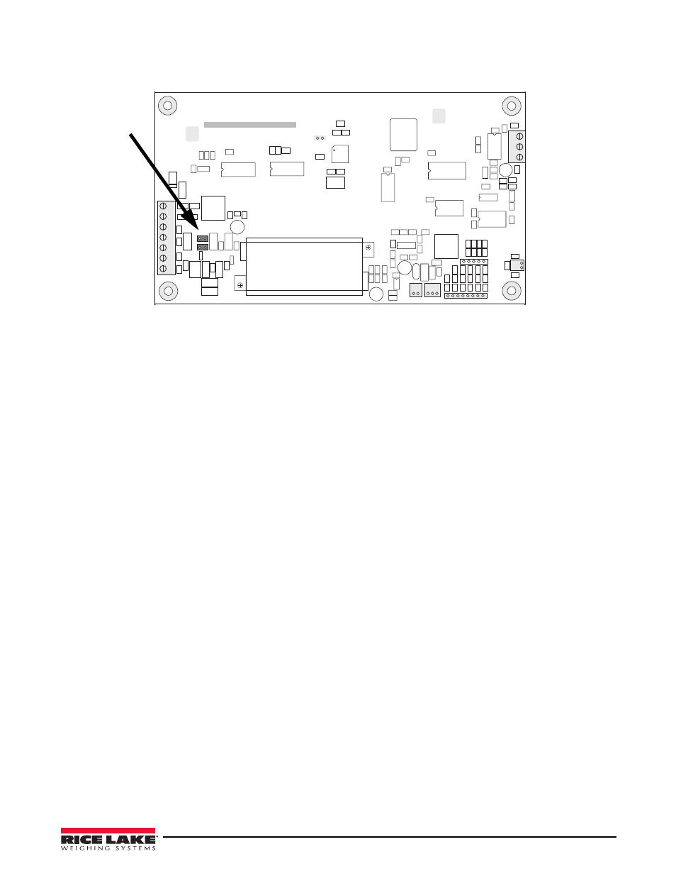
12.If using a 6-wire load cell cable (with sense wires), remove jumpers JP1 and JP2 before reinstalling connector
J1 (see Figure 4-8). For 4-wire installation, leave jumpers JP1 and JP2 on.
R12
C34
C33
D3
D4
RN
1
C40
C38
C36
C39
C35
R23
C72
C73
C71
C74
C78
C76
R27
R28
C81
C83
R24
R25
R31
D5
F1
C80
EMI1
R46
R45
R44
R40
R39
R38
R37
C92
C91
C90
R34
R33
R43
C84
C85
U15
C77
VR2
D1
R2
C31
C32
R1
C1
L2
C28
U1
VR
1
L1
C13
C6
R7
C10
C9
R26 C79
C75
U6
C14
R32
R29
C82
C2
XT1
C4
C8
C7
C3
C5
R6
R5
R3
R4
C41
R15
R14
C37
C42
Q1
C11
C12
R30
C86
C87
C15
U12
U10
U7
U11
R8
C17
C18
C19
R9
C16
C20
C27
U9
C88
C89
VR4
U8
R49
R50
C95
R48
R42
R41
C94
C93
R35
R36
R47
RICE LAKE WEIGHING SYSTEMS
1
RESET
AGND
DGND
+SIG
–SIG
+SENSE
–SENSE
SHIELD
+EXC
–EXC
1
2
3
4
5
6
7
LOAD CELL
CONNECTOR
J1
JP2
JP1
D2
J5
Keypad Connector
1
J4
J2
TxD
GND
RxD
1
2
3
SERIAL PORT
1
J3
Battery
Input
AC
Adapter
Input
1
J6
To Setup
Switch
A / D C o n v e r t e r
GND
GND
1
J7
VR3
U4
Microcontroller
U5
FLASH RAM
U2
U3
Display Drivers
R11
C29
R13
C30
RN
2
+
+
+
C26
C23
C25
R10
C21
C22
C24
+
Figure 4-8. IQ Plus 390-DC Indicator Board
4.3
Final Adjustment, Calibration and Troubleshooting
Final adjustment, calibration and troubleshooting of the IQ Plus 390-DC indicator can be found in the IQ Plus
390-DC Installation Manual, PN 48820.