Rice Lake Star SP298 Series Programmers Manual User Manual
Page 53
50
“!”
1B
21
Select line mode (default)
If this command is specified while in page mode, printing is not
carried out and the printer returns to line mode.
“*”
X
L
X
H
Y
L
Y
H
dX
L
dX
H
dY
L
dY
H
1B
2A
X
L
X
H
Y
L
Y
H
dX
L
dX
H
dY
L
dY
H
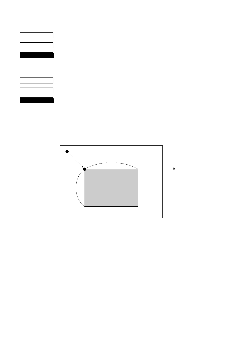
Setting print area in page mode
The coordinates of the current position at the moment that page
mode is entered are (0,0). The starting point of the print area is
defined by X
L
, X
H
, Y
L
and Y
H
. In addition, the length DX in the X
direction is specified by dX
L
and dX
H
, and the length DY in the Y
direction is specified by dY
L
and dY
H
.
Starting point X
0
= X
L
+ (X
H
×
256) dots
Starting point Y
0
= Y
L
+ (Y
H
×
256) dots
Length in horizontal direction DX = dX
L
+ (dX
H
×
256) dots
Length in vertical direction DY = dY
L
+ (dY
H
×
256) dots
The values of XL, YL, dXL and dYL are between 0 and 255, and the
values of XH, YH, dXH and dYH are between 0 and 1.
However, dXL = dXH = 0 and dYL = dYH = 0 are not included.
In addition, since the maximum range in the X direction (X
O
+ DX)
is 210 dots and the maximum range in the Y direction (Y
O
+ DY) is
720 dots, each parameter should be specified to satisfy these ranges.
When the power is turned on, XL = XH = YL = YH = 0 (X
O
,Y
O
=
0,0)
dXL = 210, dXH = 0 (DX = 210) and
dYL = 64, dYH = 2 (DY = 576).
CODE
HEX
FUNCTION
CODE
HEX
FUNCTION
Paper feed direction
Current position (0,0)
Print area
DY
DX
(X
0
,Y
0
)
- 1010 Potted & Unpotted Single Point, Aluminum (58 pages)
- 120 Digital Weight Indicator (44 pages)
- 120 Plus Digital Weight Indicator (56 pages)
- 320IS Intrinsically-Safe Digital Weight Indicator - Installation Manual (76 pages)
- 320IS Intrinsically-Safe Digital Weight Indicator - Timer Relay Instruction Sheet (2 pages)
- 320IS Intrinsically-Safe Digital Weight Indicator - Battery Charging Instruction Sheet (2 pages)
- 320IS Intrinsically-Safe Digital Weight Indicator - I/O Module for Intrinsically Safe Systems Installation Manual (15 pages)
- 320IS Intrinsically-Safe Digital Weight Indicator - IS-6V Battery Pack Instruction Sheet (6 pages)
- 320IS Intrinsically-Safe Digital Weight Indicator - IS-EPS-100-240 Power Supply Instructions (6 pages)
- 320IS Plus Intrinsically Safe Digital Weight Indicator - Installation Manual (90 pages)
- 420 Plus HMI Digital Weight Indicator Installation Manual (60 pages)
- 420 Plus HMI Digital Weight Indicator Operator Card (3 pages)
- 420 Plus Digital Weight Indicator - 7.5V DC-to-DC Power Supply Installation (4 pages)
- 420 Plus Digital Weight Indicator - IQ plus 355 - 390-DC - 590-DC & 420 Plus Quick Connector Cable Installation Instructions (1 page)
- 480 Legend Series Digital Weight Indicator Installation Manual (68 pages)
- 480 Legend Series Digital Weight Indicator Operator Card (1 page)
- 480 Panel Mount Option (4 pages)
- 520 Analog Output Card Installation (2 pages)
- 520 Digital Weight Indicator Operator Card (4 pages)
- 520 HMI Digital Weight Indicator Installation Manual (98 pages)
- 520 HMI Digital Weight Indicator Manual - BCD Option (18 pages)
- 520 Configurable Weight Indicator - Remote I/O Indicator Interface Installation and Programming Manual (31 pages)
- 520 Configurable Weight Indicator - ControlNet Interface Installation and Programming Manual (23 pages)
- 520 Configurable Weight Indicator - DeviceNet Interface Installation and Programming Manual (21 pages)
- 520 Configurable Weight Indicator - Ethernet Interface Installation and Configuration Manual (38 pages)
- 520 Configurable Weight Indicator - EtherNet/IP Interfac Installation and Programming Manual (26 pages)
- 520 Configurable Weight Indicator - Profibus DP Interface Installation and Programming Manual (21 pages)
- 550-10-1 Digital Chair Scale - Operation Manual (26 pages)
- 550-10-1 Digital Chair Scale - Technical Manual (34 pages)
- 590-AG Livestock Digital Weight Indicator (56 pages)
- 65059 Mild Steel 3-Module Kit - RL50210 Load Cell Mounting Kit Installation Guide (13 pages)
- 720i Programmable Indicator/Controller - 6V DC-to-DC Power Supply Installation Instructions (4 pages)
- 720i Programmable Indicator/Controller - Installation Manual (122 pages)
- 720i Programmable Indicator/Controller - Operator Card (4 pages)
- 720i Programmable Indicator/Controller - Analog Output Card Installation Instructions (4 pages)
- 720i Programmable Indicator/Controller - CW-90/90X - iQUBE2 - LaserLT WLAN Installation Instructions (12 pages)
- 720i Programmable Indicator/Controller - USB Interface Card Installation Instructions (2 pages)
- 820i Programmable Indicator/Controller - Installation Manual (112 pages)
- 820i Programmable Indicator/Controller - Panel Mount Enclosure Installation Instructions (6 pages)
- 880 Performance Series Indicator/Controller Operators Manual (36 pages)
- 880 Performance Series Indicator/Controller Technical/Service Manual (120 pages)
- 880 Performance Series Panel Mount Indicator/Controller - Adapter Panel Installation (4 pages)
- 880 Performance Series Panel Mount Indicator/Controller - Analog Output Card Option Installation Manual (6 pages)
- 880 Performance Series Panel Mount Indicator/Controller - DeviceNet Interface Option Installation and Programming Manual (28 pages)
- 880 Performance Series Panel Mount Indicator/Controller - EtherNet/IP Interface Option Installation and Programming Manual (32 pages)