5 typical application, Typical application, Figure 4 application examples – Rice Lake SURVIVOR Paramounts HE Medium Capacity User Manual
Page 7: Caution, Paramount installation guide 3, Typical module application for cylindrical vessels
Paramount Installation Guide
3
1.5 Typical Application
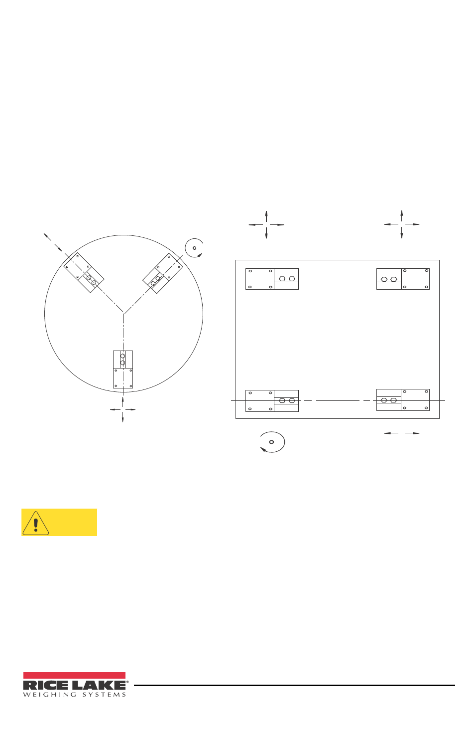
The sample installations shown in Figure 4 demonstrate the basic principles
involved with module applications. Arrows by each mount indicate the directions
that the top plate for that mount can move. When arranged as illustrated, the posi-
tion of the vessel is fixed at one point by the fixed pin mount. The side stop mount
allows for thermal expansion/contraction in the direction of the arrows while
checking movement in other directions. Free sliding mounts allow for expansion
in all directions. This arrangement ensures that there is minimal binding or side
loading of the load cells. At the same time, the system is self-checking.
FREE SLIDING
MOUNT
SIDE STOP
MOUNT
FIXED PIN
MOUNT
FREE SLIDING
MOUNT
SIDE STOP
FIXED PIN
FREE SLIDING
MOUNT
Typical module application
for cylindrical vessels.
Figure 4 Application Examples
With tall, slender vessels or in areas with earthquake activity or high
winds, safety may require additional vessel restraints in the form of
stay rods or safety check rods.
CAUTION