3 physical dimensions, 4 mount configurations, Physical dimensions mount configurations – Rice Lake SURVIVOR Paramounts HE Medium Capacity User Manual
Page 6
2
Paramount Installation Guide
1.3 Physical Dimensions
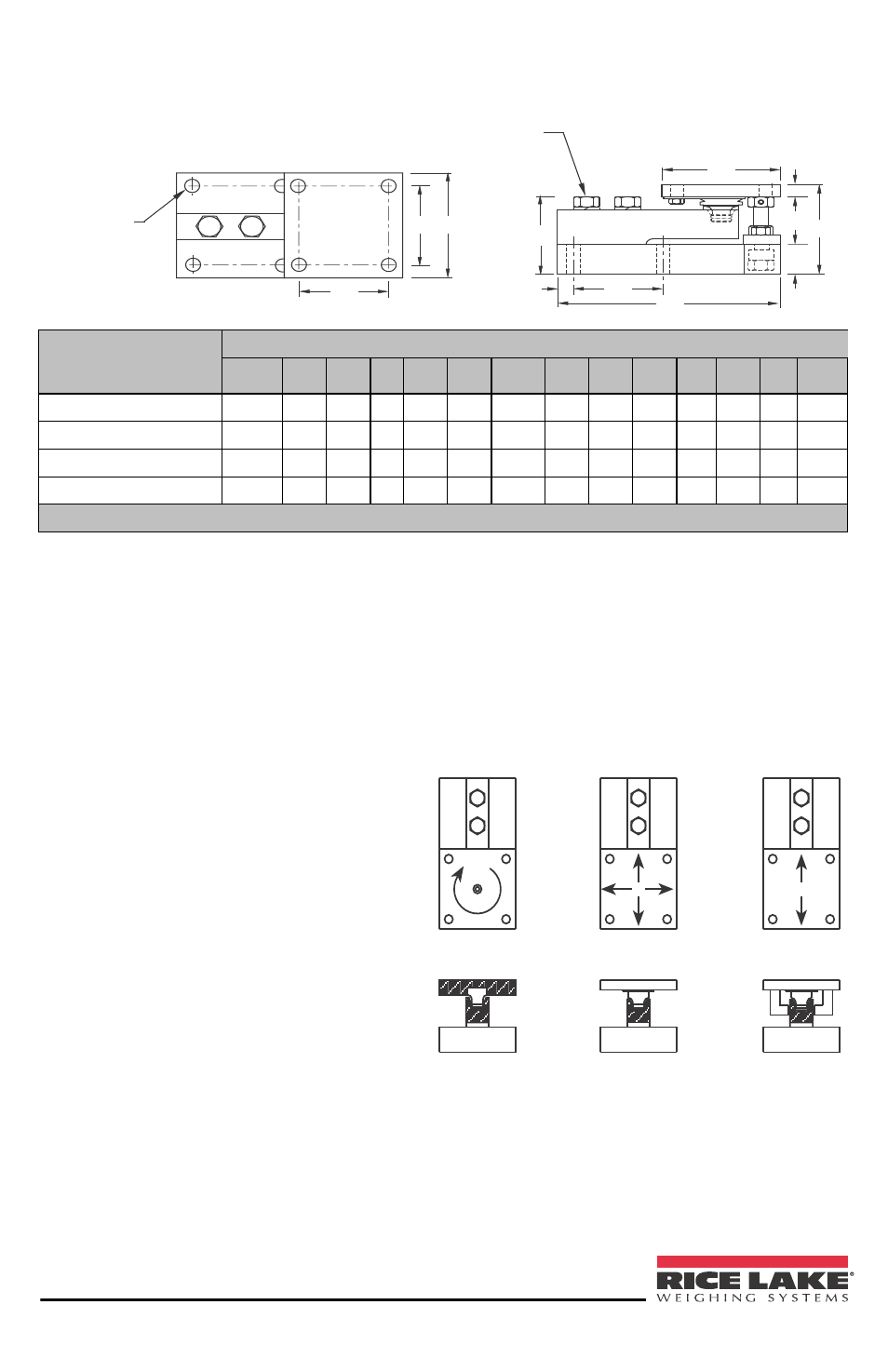
Figure 2 Physical Dimensions
1.4 Mount Configurations
When installed according to the guidelines in this manual, the Paramount kit
allows for thermal expansion/contraction of the weighing vessel while keeping the
vessel in check without the use of check rods in many applications. A clear under-
standing of the function of each of the three types of mounts is necessary in plan-
ning your installation.
FIXED PIN
FREE SLIDING
SIDE STOP
Figure 3 Mount Configurations
Free sliding and side stop mounts have loading pins with teflon coated top sur-
faces that slide on stainless steel plates attached to the underside of the top plates.
This combination allows the top plates to move freely as indicated by the arrows.
D (8 PLS)
L1
W1 W
H3
L4
Torque Q ft-lb
L3
L2
L
H1
H2
H
Rated Capacity
Dimensions - Inches
D
H
H1 *H2 **H2 H3
L
L1
L2
L3
L4
W
W1
Q
(ft-lb)
520 lb (1-2.3 KN)
0.37
3.49 1.00 .50 .75 2.98 7.51 3.00 4.00 3.00 .50 4.00 3.00 65
1125-5200 lb (5-23 KN) 0.437 3.58 1.25 .50 .75 3.06 7.51 3.00 4.00 3.00 .50 4.00 3.00 65
11,250 lb (50 KN)
0.562 4.66 1.50 .62 1.00 4.09 9.19 3.87 5.00 3.87 .56 5.00 3.87 295
22,500 lb (100 KN)
0.688 6.41 2.00 .75 1.25 5.73 11.46 4.75 6.00 4.75 .69 6.00 4.75 515
NOTES: *H2 is for side stop and free-floating units; **H@ is for fixed pin units; KN = Kilonewtons
• Fixed pin mount: eliminates all hori-
zontal movement of the top plate
except rotation around the loading
pin.
• Free sliding mount: allows horizontal
movement of the top plate in all
directions.
• Side stop mount: allows horizontal
movement of the top plate only along
the axis of the load cell.