0 trimming & calibrating, Trimming & calibrating – Rice Lake AX 3040 User Manual
Page 14
10
AX3040 Operator Manual
4.0
Trimming & Calibrating
The Rice Lake AX3040 is delivered with the junction box corner-trimmed. However, once the weigh pads have
been set up, you may want to verify that end weight values on each weigh pad are the same. We suggest you use
25% of the weigh pad capacity for verification. Provided the values are the same, you can perform calibration using
25% of the Rice Lake AX3040 total capacity. Take care to distribute the test weights evenly across the two weigh
pads. Refer to the indicator manual to determine correct calibration procedures.
Trimming Procedure
Trimming is a process of equalizing the output from multiple individual load cells. If needed, load cell output can
be individually trimmed with potentiometers.
Whenever a substantial amount of trim (more than 5% of normal output), seems necessary to equalize output,
check for other possible problems. The best trim is always the least amount of trim. When all errors except cell
mismatch and cable extensions or reductions have been corrected, continue with the trimming.
Use the following steps to properly trim the junction box.
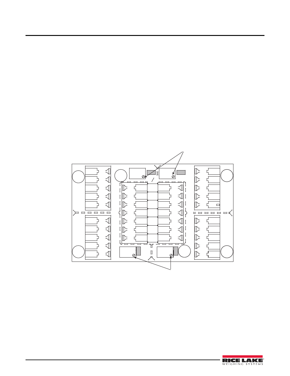
1. Make sure jumpers are in place to enable trimming of the cells corresponding to each load cell. See Figure
4-1 for the location of jumpers JP1, JP2, JP3, and JP4. Note that you need to remove jumpers for any
unused cells.
Set all potentiometers fully clockwise to give maximum signal output from each cell (See Figure 4-1 for
location of potentiometers).
JP4
JP2
PT4
PT3
JP3
PT1
EXP
PT2
JP1
1
CELL4
1
CELL1
1
CELL3
1
CELL2
IND
-EX
-SI
SHD
+SI
+EX
M
R
N
I
-SI
S2C
I
A
G
+EX
+SI
-SI
SHD
-EX
I
S
G
A
L
T
+SI
M
S
I
N
L
T
R
+EX
-EX
-SI
SHD
+SI
+EX
+SI
-EX
-SI
SHD
-EX
SHD
+SE
-SE
+EX
Potentiometers
Jumper Locations
JP1 and JP2
Shaded
Jumper Locations
JP3 and JP4
Shaded
Potentiometers
1
1
Load cells will be
wired in on Cell 1
and Cell 4
Figure 4-1. Potentiometer Locations
2. Zero the indicator and place calibrated test weights over each load cell one at a time. The amount of test
weight to be used will depend on the configuration. Rice Lake Weighing Systems suggest you use 25% of
the weigh pad capacity.
3. Record the value displayed on the indicator after each test weight is placed one at a time on each end
(directly over the load cell) without allowing the weight to overhang the sides. Allow the AX3040 to return
to zero each time to check for friction or other mechanical problems. Select the load cell that has the lowest
value as your reference point. This cell will not be trimmed and will be your reference load cell.
4. Place the same test load over each cell one at a time. Using the corresponding potentiometer, trim each cell
down to equal the reference load cell. As end corrections are somewhat interactive, check all cells again for
repeatability. If necessary, repeat steps 4 and 5.