Wall mount installation – Rice Lake 920i Six Card Expansion Board User Manual
Page 2
2
920i
Six-Card Expansion Board Installation Instructions
Wall Mount Installation
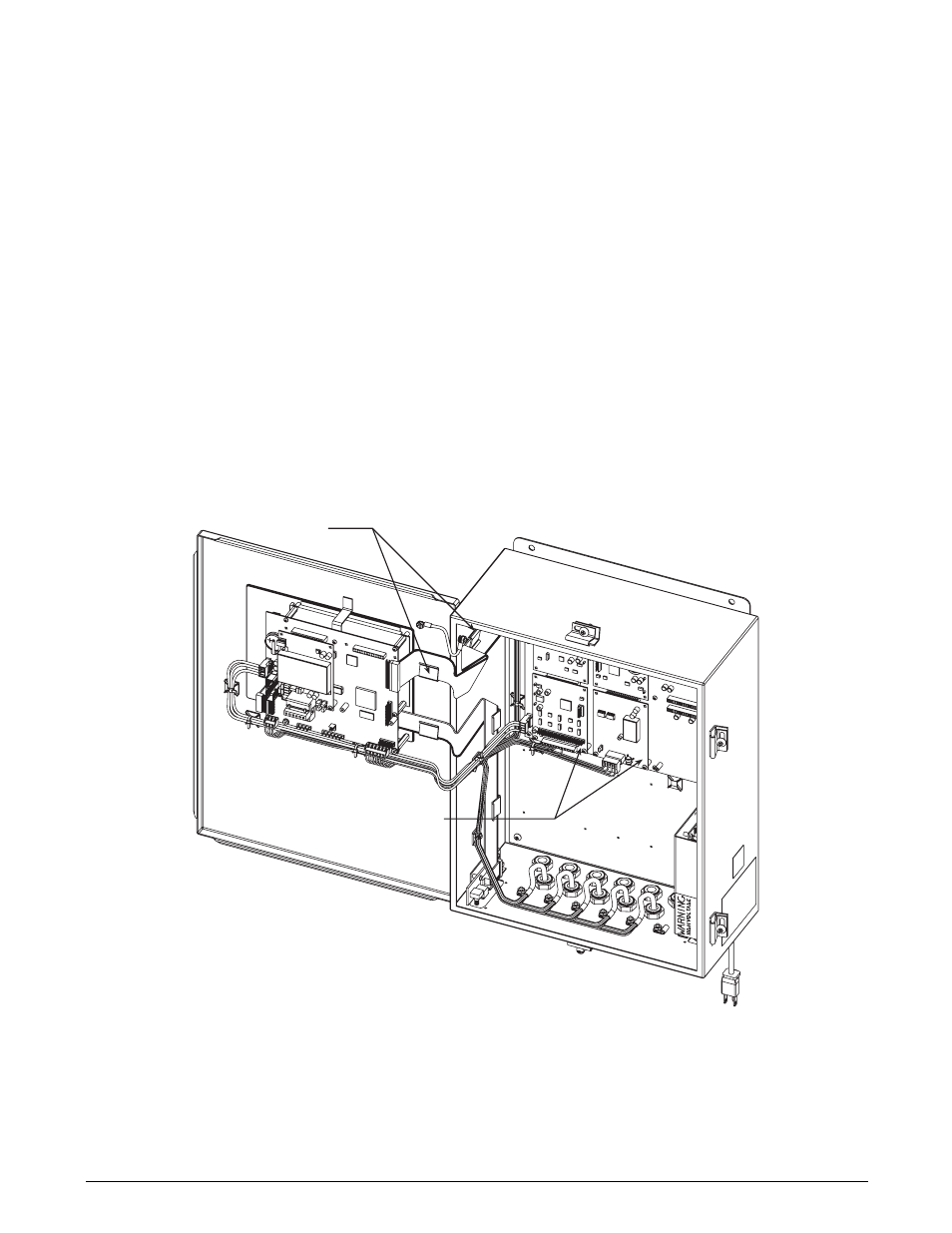
Use the following procedure to install the six-card
expansion board in the wall mount enclosure. See
Figure 2 below and Figure 3 on page 3 for locations of
option kit components.
1. Disconnect indicator from power source.
2. Open enclosure.
3. Clip the six cable ties that secure the cable
assembly from the power supply to the CPU
board. Remove power supply cable.
4. Remove adhesive covering from two ribbon
cable clamps and install on door and side wall
of enclosure (see Figure 2 on page 2).
5. Mount six-card expansion board on studs at
back of enclosure. Use ten 1/4" screws (PN
14839) to secure board to studs (see Figure 3
on page 3 for screw locations).
6. Attach ribbon cable to connector J7 on the
CPU board, with the striped edge of the cable
on the pin 1 side of the connector. (See
Figure 3 on page 3 for connector and pin
locations.)
7. Slide the ribbon cable into the cable clamps
and attach to connector J1 on the expansion
board, with the striped edge of the cable on the
pin 1 side of connector J1. Note that the ribbon
cable must be folded (see Figure 2) for correct
orientation at the connector.
8. Attach long power cable assembly from
connector J9 on the expansion board to the
power input on the CPU board.
9. Attach short power cable assembly from power
supply to connector J10 on the expansion
board.
10. Set the slot/location jumper to the 3–8 position
(see Figure 1 on page 1).
11. Install option cards onto expansion board (see
page 3). Use the supplied cable ties to secure
all loose cables inside the enclosure.
Figure 2. Six-Card Expansion Board Installed in Wall Mount Enclosure, Isometric View
RIBBON CABLE
CLAMPS
INSTALLED
OPTION CARDS
ON SIX-CARD
EXPANSION BOARD