Rice Lake 920i Six Card Expansion Board User Manual
Six-card expansion board installation instructions, 920i, Programmable hmi indicator/controller
January 2005
71285
920i
™
Programmable HMI Indicator/Controller
Six-Card Expansion Board Installation Instructions
PN 69783
This document contains procedures used to install
six-card expansion boards in wall mount models of
920i
indicators.
See the
920i
Installation Manual, PN 67887, for
general installation and configuration information,
including option card slot numbering and port
assignments.
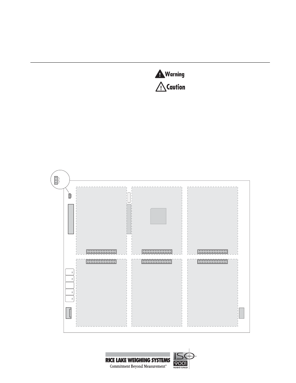
NOTE:
The slot/location jumper on the six-card
expansion board must be set to the 3–8 position for all
standard installations. The 9–14 jumper position is
used only in special applications using two six-card
expansion boards.
For applications using two six-card expansion boards,
use cable PN 87164 to connect the J2 connector on the
first board (slots 3–8) to J1 on the second board (slots
9–14).
Disconnect power before opening indicator
enclosure.
Use a wrist strap to ground yourself and
protect components from electrostatic
discharge (ESD) when working with circuit
boards.
Option cards are not hot-pluggable. Disconnect power to the
expansion board before installing option cards.
Ensure that option cards are aligned with standoffs and
installed on the correct connector. Installing cards on the
adjacent connector (for example, plugging a card intended for
J6 onto the J3 connector) may damage the card.
Figure 1. Six-Card Expansion Board
J3
J4
J5
J7
J6
J9
J1
J10
1
J8
+6V
–6V
ISP
1
J2
1
1
1
+3.3V
+5V
GND
+6V
–6V
POWER IN
POWER OUT
U3
SLOT/LOCATION JUMPER
9–14
3–8
9–14
3–8
GND
GND
–6V
+6V
GND
GND