Voltage/current selection and wiring, Enclosure reassembly, Configuration – Rice Lake 920i Dual Channel Analog Input Card User Manual
Page 4
4
920i
Analog Input Card with Thermocouple Input Installation Instructions
Voltage/Current Selection and Wiring
Set the mode select jumpers (Select 1
SEL1
and Select 2
SEL2
on option board), (see Figure 6) for input. Set
jumpers to I if using 4-20mA or V if using 0-10 V.
When using the +/- 10 volt or the 0-20 mA ranges, the option card selection jumpers should be set to the
appropriate setting. The following table lists the voltage and current selections
NOTE: Only one input is available per connector, two channels per option card, with the exception of the low level input channel, J3.
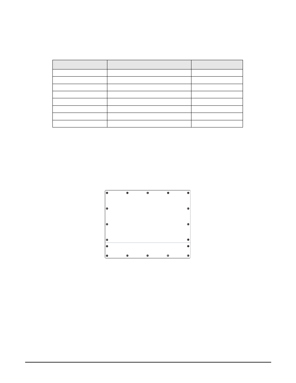
Enclosure Reassembly
Once cabling is complete, position the backplate over the enclosure and reinstall the backplate screws. Use the
torque pattern shown in Figure 7 to prevent distorting the backplate gasket. Torque screws to 15 in-lb (1.7 N-m).
1. Ensure no excess cable is left inside the enclosure and tighten cord grips.
2. Reconnect power to the indicator.
Figure 7 Enclosure Backplate
The
920i
automatically recognizes all installed option cards when the unit is powered on.
Configuration
The analog input option must be installed for the ALGIN menu to be displayed.
Front Panel Configuration
Use the CONFIG submenu under the SCALES menu to configure A/D scales. For example, in an indicator with an
analog input card installed in Slot 1, the scale configuration display will show the A/D listed (
Slot 1 Channel 1 and
Slot 1 Channel 2
) under the
AVAILABLE A/D’s
column.
NOTE: Select only one A/D per scale.
Connection
Function
Range
J1-1
V1, +
+/–10 V
J1-2
V1, –
+/– 10 V
J1-3
I1, +
0-20 mA
J1-4
I1, –
0-20 mA
J2-1
V2, +
+/– 10 V
J2-2
V2, –
+/– 10 V
J2-3
I2, +
0-20 mA
J2-4
I2, –
0-20 mA
Table 3 Voltage and Current Selections
1
3
5
14
17
16 12
9
8
7
10
11
18
15
4
2
6
13
Torque backplate screws
to 15 in-lb (1.7 N-m)