Thermocouple wire installation – Rice Lake 920i Dual Channel Analog Input Card User Manual
Page 2
2
920i
Analog Input Card with Thermocouple Input Installation Instructions
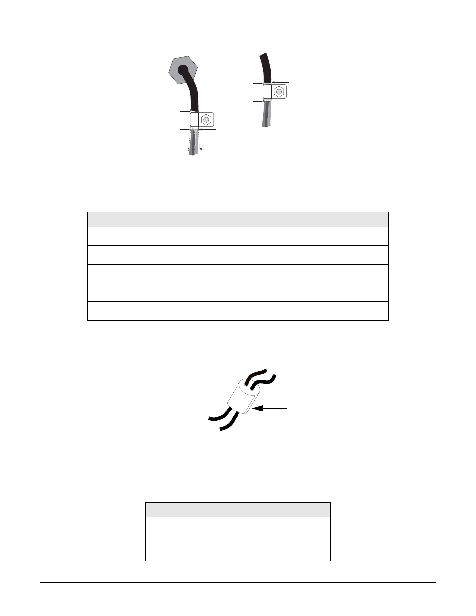
Figure 3 Grounding Clamp Attachment for Foil-Shielded Cabling and Braided Cabling
Thermocouple Wire Installation
There are five different types of thermocouple probes that are supported by the
920i
. Table 1 lists the various
thermocouple probe types, their corresponding wire colors, and their temperature ranges.
Use the following instructions to connect thermocouple cables in indicators.
1. Insert the multi-cable bushing (PN 73997), into one of the available cord grips on the
920i
located closest to
the analog input option (See Figure 6 on page 3.).
Figure 4 Multi-Cable Bushing
2. Route the thermocouple wire through one of the holes in the multi-cable bushing (Figure 4).
3. Strip 1/4-inch of insulation from the end of the thermocouple cable.
4. Install wires into the J3 connector on the analog input option card as shown in Table 2 on page 3. Depending
upon the type of cable used, the wire colors will differ however, the
–
signal will always be red wire. See
Thermocouple Cable Type
Typical Corresponding Wire Colors
Temperature Range
Type E
+ Purple
– Red
-454 – 1832°F
(-270 – 1000°C)
Type J
+ White
– Red
-346 – 2192°F
(-210 – 1200°C)
Type K
+ Yellow
– Red
-454 – 2501.6°F
(-270 – 1372°C)
Type N
+ Orange
– Red
-454 – 2372°F
(-270 – 1300°C)
Type T
+ Blue
– Red
-454 – 752°F
(-270 – 400°C)
Table 1 Thermocouple Wire Identification
J3 Connector Pin
Function
1
T1/mV +
2
T1/mV –
3
T2/mV +
4
T2/mV –
Table 2 Thermocouple and +/– 100 mV Pin Assignments
$PSEHSJQ
*OTVMBUFEDBCMF
'PJM TJMWFSTJEFPVU
(SPVOEJOHDMBNQ
4IJFMEXJSF DVU
-FOHUIPGGPJMCFGPSFGPMEJOH
CBDLPODBCMFJOTVMBUJPO
$VUJOTVMBUJPOIFSF
GPSGPJMTIJFMEFEDBCMFT
#SBJE
$VUJOTVMBUJPOIFSF
GPSCSBJEFEDBCMFT
/05&*OTUBMMMPDLXBTIFST
mSTU BHBJOTUFODMPTVSF
VOEFSHSPVOEJOHDMBNQ
Thermocouple Wires
Sealing Plug