0 installation, 1 installing the profibus dp interface, Installation – Rice Lake 920i Programmable HMI Indicator/Controller - Profibus DP Interface User Manual
Page 6
2
520/720i/820i/920i
Profibus DP Installation and Programming Manual
2.0
Installation
The Profibus DP Interface hardware consists of a
dual-board option card. Profibus-specific functions
a r e p r o v i d e d b y a P r o f i b u s m o d u l e , w h i c h i s
factory-installed onto a bus adapter card. The bus
adapter card plugs into an open option card slot on the
520
,
720i
,
820i
, or
920i
CPU board (or expansion
board) and provides power and access from the
indicator bus to the Profibus module.
This section describes the procedures used to install
the Profibus DP Interface into the
520
,
720i
,
820i
, and
920i
indicators, connect communications cables, and
set the address and bus termination switches on the
Profibus module.
2.1
Installing The Profibus DP Interface
Use the following procedure to install the Profibus DP
Interface into
520
,
720i
,
820i
, and
920i
indicators.
1. Disconnect indicator from power source.
Disconnect power before removing
indicator backplate.
The
520
,
820i
,
and
920i
have no on/off
switch. Before opening the unit, ensure the
power cord is disconnected from the
power outlet.
2. Open indicator enclosure. For indicator models
with backplates, place indicator face-down on
an antistatic work mat. Remove screws that
hold the backplate to the enclosure body.
Use a wrist strap to ground yourself and
protect components from electrostatic
discharge (ESD) when working inside the
indicator enclosure.
3. Carefully align the large connector (J1) on the
bus adapter card with connector J5 or J6 on the
920i
CPU board, J6 on the
820i
CPU board,
connector J2 on the
520
CPU board, or
connector J12 on the
720i
. Press down to seat
the bus adapter card in the CPU board
connector.
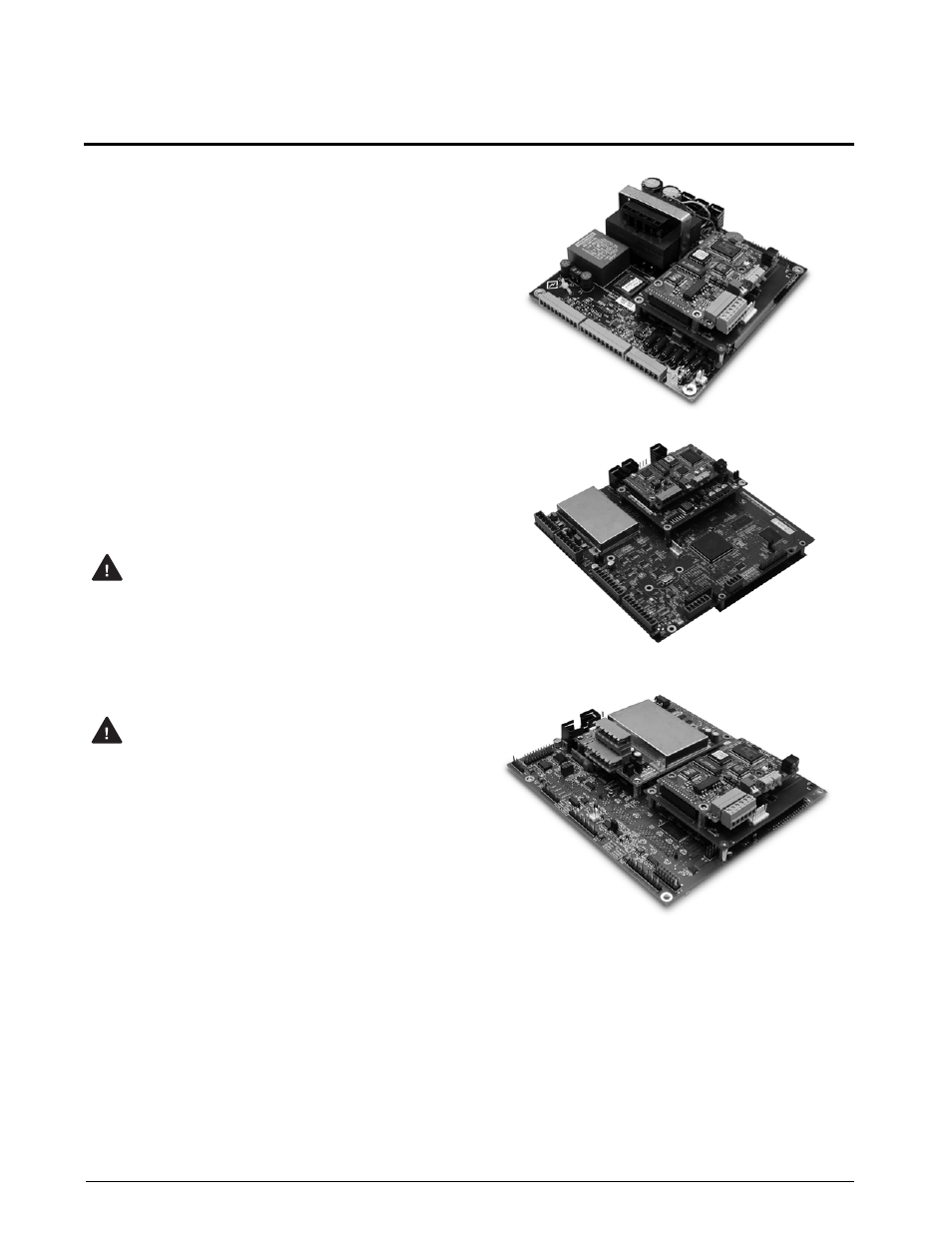
4. Use the screws and lockwashers provided in
the option kit to secure the other end of the
option card to the threaded standoffs on the
CPU board (see Figures 2-1, 2-2, and 2-3).
5. Wire the card to the network as described in
6. Set address switches and termination switch
as described in Section 2.3 on page 4.
7. Use cable ties to secure loose cables inside the
enclosure.
Figure 2-1. Option Installed on
520 CPU Board
Figure 2-2. Option installed on
820i CPU Board
Figure 2-3. Option Installed on
920i CPU Board
8. For indicator models that include a backplate,
position the backplate over the enclosure and
reinstall the backplate screws. For the
920i
desktop and universal models, use the torque
pattern shown in Figure 2-4 on page 3 to
prevent distorting the backplate gasket.
Torque screws to 15 in-lb (1.7 N-m).
W arning
W arning