Bag c – Losi LOSA0095 Manual User Manual
Page 12
47
26
23
25
55
53
165
49
48
52
50
41
54
164
19
122
17
17
51
BAG C
8
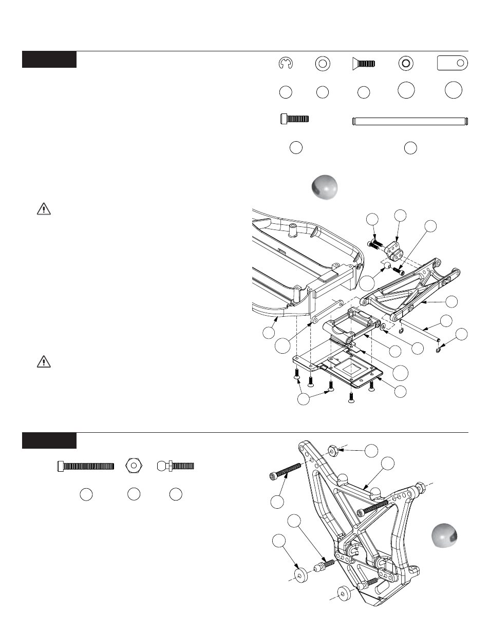
Figure 18
Figure 19
!
Step 1. Insert a 1/8" x 1/4" washer (48) into the recessed area
on each side of the rear pivot block (49).
!
Step 2. Place one of the rear suspension arms (50) over the
right side of the rear pivot block (49). Line up the holes in the
arm (50) with the holes in the pivot block (49) and assemble the
two parts by inserting an inner rear hinge pin (52) all the way
through both parts. Install a 1/8" E-clip (41) to the rear end of the
hinge pin (52).
!
Step 3. Attach a 1/4" shock mount ball (122) to the inside
hole of the shock mount bracket (51) with a 4-40 x 3/8" cap-head
screw (17) as shown in Figure 18. Secure the shock mount bracket
(51) to the front side of the rear suspension arm (50) with two
4-40 x 3/8" cap-head screws (17).
IMPORTANT NOTE: Ensure that the shock mount
bracket is attached correctly. The outside holes should be higher
than the inside holes. The shock mount ball should be to the
rear side of the bracket.
!
Step 4. Repeat Steps 1-3 for the left suspension arm (50).
!
Step 5. Slide the rear hinge pin brace (164) over the front of
both inner hinge pins (52). Secure the brace (164) by attaching a
1/8" E-clip (41) to the front of each hinge pin (52).
!
Step 6. Place a small anti-squat shim (165) under front of
each side of the rear of the pivot block (49) as shown in Figure
18. Attach the rear pivot block (49) and shims (165) to the rear
pivot plate (53) with four 4-40 x 3/8" flat-head screws (54).
!
Removing the shims results in 2
o
anti-squat. Anti-squat
is 4
o
with the shims in place. See the anti-squat section of the tips.
IMPORTANT NOTE: Ensure that the pivot block is
installed with the wider end to the rear as shown in Figure 18.
!
Step 7. Install the rear pivot plate (53) so that the pivot plate
(53) is flush with the chassis (19). Make sure that the four holes in
the chassis (19) line up with the holes in the pivot plate (53).
Secure the pivot plate (53) to the chassis (19) using four 4-40 x
3/8" flat-head screws (54).
!
Step 8. Insert two 4-40 x 7/8" cap-head screws (23) — one on
each side — through the second hole out on the top of the rear
shock tower (55) as shown in Figure 19. Secure the screws (23) to
the shock tower (55) by threading a 4-40 nut (25) over each screw
(23) and tightening.
!
Use the included Team Losi wheel wrench/nut-driver
to secure the 4-40 nuts.
!
Step 9. Thread a 3/8" ball stud (26) into the center hole on
each side of the rear shock tower (55). Place a “foam thing” (47)
over each of the two ball studs (26).
Figure 18
Figure 19
23
25
26
41
48
54
165
122
52
17