Chapter 4 programming pb-tim2 user’s manual – Kontron PB-TIM2 User Manual
Page 22
Chapter 4 Programming
PB-TIM2 User’s Manual
4.2 Register Allocation
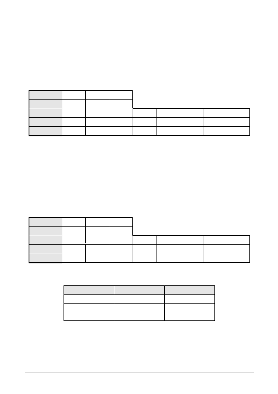
4.2.1 Channel Control Register
Write Only Register
Channel
0
1
2
Address
$01
$21
$41
Bit
7
6
5
4
3
2
1
0
Function
Load
Enable
Clear
After Reset
0
0
0
0
0
0
0
0
Where •
Clear :
Clears the timer (all 0’s) and the output (Toggle flip-flop) when this bit is set
to
1
• Enable :
Enable timer operation (i.e. starts the timer or single measurement when this
bit
is set to 1
• Load :
Loads the timer with the Comparator/Preset register value when set to 1
4.2.2 Channel Mode Register
Write Only Register
Channel
0
1
2
Address
$05
$25
$45
Bit
7
6
5
4
3
2
1
0
Function
Output
Reload
Mode 1
Mode 0
B IN 1
B IN 0
A IN 1
A IN 0
After Reset
0
0
0
0
0
0
0
0
Where • A IN 0 and 1 :
Defines the input mode
A IN 1
A IN 0
Mode
0
0
Rising Edge
0
1
Falling Edge
1
x
Both Edges
• B IN 0 :
Defines input (B) level or edge
0 active high - rising edge
1 active low - falling edge
• B IN 1 :
Defines input (B) level or edge
0 level
1 edge operation
Page 4-2
© 1996 PEP Modular Computers
July 30, 1997
- CP3003-SA uEFI BIOS (72 pages)
- CP3003-SA (36 pages)
- CP3002 (38 pages)
- CP3002-RC uEFI (64 pages)
- CP-RIO3-05 (42 pages)
- CP3002-RC (30 pages)
- CP342 (52 pages)
- CP930 (46 pages)
- CP932 (52 pages)
- CP346 (72 pages)
- CP384 (66 pages)
- CP383 (74 pages)
- CP382 (58 pages)
- CP381 (60 pages)
- CP372 (64 pages)
- CP371 (60 pages)
- CP-RIO3-04S (38 pages)
- CP390 (36 pages)
- CPS3410 (9 pages)
- CPS3402 (9 pages)
- CPS3105 (9 pages)
- CPS3101 (9 pages)
- CPS3003-SA (19 pages)
- PB-SIO4 (34 pages)
- PB-SIO4A (34 pages)
- PB-DOUT8 (34 pages)
- VMOD-2 (82 pages)
- VSBC-32 (110 pages)
- VM42 (62 pages)
- Bootstrap Loader (24 pages)
- VMP1 with Netbootloader (120 pages)
- VMP1 (106 pages)
- NetBootLoader (86 pages)
- VMP2 (142 pages)
- VMP3 (154 pages)
- CP-RIO6-923 (32 pages)
- CP-RIO6-923-F (32 pages)
- CP-RIO6-001 (28 pages)
- CP-RIO6-001-HD-VGA (46 pages)
- CP-RIO6-M (20 pages)
- CP-RIO6-B (28 pages)
- CP6925 (42 pages)
- CP6002 uEFI BIOS (76 pages)
- CP6002 IPMI (40 pages)
- CP6002 (42 pages)